
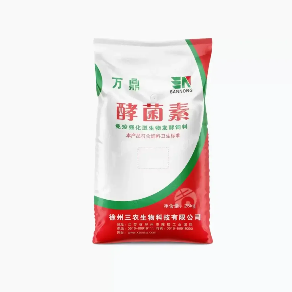
- What Are Tubular FFS Films?
- Common Aliases and Industry Terminology
- Key Features That Define High‑Performance Tubular FFS Films
- From Resin to Roll — The Production Process Behind Performance
- Where Tubular FFS Films Win — Applications and Use‑Cases
- Standards, Certifications, and Third‑Party Verification
- Engineering Details — Designing a Specification That Runs
- At‑a‑Glance Specification Matrix for Plant Engineers
- FFS Line Integration — Practical Guidance for Smooth Start‑ups
- Sustainability and Compliance by Design
- Quality Documentation — What Buyers Receive
- Why VidePak — Differentiators That Matter on the Line
- Procurement Checklist — Faster Approvals and Fewer Revisions
- Risk Controls — Designing for Real‑World Abuse
- Case‑Ready Language for Your Datasheets and RFPs
- How to Engage VidePak — From Trial to Global Rollout
- Your Next Step
- Framing the Packaging Problem the Way Engineers Actually See It
- How Tubular FFS Films Alter Friction, Flow, and Fill — The Local Topography Argument
- Why Entrapped Air Inflates Cost Curves — Vent Logic for Tubular FFS Films
- The System View: When Grip Meets Vent in Tubular FFS Films
- Inside the Wall: Layer Design of Tubular FFS Films That Survive Rough Handling
- Machine Integration Is a Dialogue — Tubular FFS Films Matching to Shoulders, Belts, and Eyes
- Health, Worker Safety, and Regulatory Signals — What Tubular FFS Films Must Prove
- Circularity Without Hand‑Waving — Recyclability Logic for Tubular FFS Films
- Parameter Benchmarks — A Working Table for Tubular FFS Films
- Use‑Case Walkthroughs — Where Tubular FFS Films Show Their Character
- Documentation Trail — Proving What Tubular FFS Films Claim
- Specification Starter for Engineers Ordering Tubular FFS Films
- Rhetorical Interlude — Questions That Clarify Tubular FFS Films Decisions
- Cross‑Domain Echoes — When Tubular FFS Films Talk to Automation, Data, and Safety
- Extended Environmental View — Carbon and Community for Tubular FFS Films
- Frequently Asked Engineering Questions about Tubular FFS Films
- Configuration Matrix — Matching Tubular FFS Films to Products and Risks
- Internal Link for Readers Exploring Options in Tubular FFS Films
- Final Practical Notes for Teams Deploying Tubular FFS Films
- Introduction: Why Heavy‑Duty Packaging Demands a Systems View
- Problem Framing: Dust, Static, and Seal Integrity in High‑Speed Filling
- Methodology: Building a Film Specification That Closes the Loop
- What Role Does a Dust Mitigation Strategy Play in Bagging with Tubular FFS Films?
- What Materials Can Tubular FFS Films Reliably Contain?
- What Is the Benefit of Gusset and Layflat Optimization in Tubular FFS Films?
- The Role of Precision in Printing and Traceability on Tubular FFS Films
- Benefits of Using Tubular FFS Films for Spare and Bulk Part Logistics
- Exploring Customization in Tubular FFS Films
- Standardized Property Windows for Tubular FFS Films in Heavy‑Duty Bagging
- Performance Enhancements: Elevating Pallet Stability with Tubular FFS Films
- Key Factors When Selecting a Tubular FFS Films Supplier
- Evaluating the Quality of Tubular FFS Films
- Seal Science: Understanding the Thermodynamics in Tubular FFS Films
- Anti‑Static and Safety: ESD‑Aware Tubular FFS Films for Fines and Pellets
- Sustainability Pathways in Tubular FFS Films
- Integration Blueprint: From Trial Roll to Standard Item
- System Decomposition: Sub‑Problems and Solutions in Tubular FFS Films
- Horizontal Synthesis: Learning Across Packaging Domains
- Vertical Synthesis: Traceability from Resin Lot to Pallet KPI
- Data‑Driven Decision Making: KPIs for Tubular FFS Films Programs
- A Unified Solution: The Integrated Playbook for Tubular FFS Films
- Practical Glossary and Internal Link
- References
What Are Tubular FFS Films?
In industrial packaging, form‑fill‑seal films in tubular format are continuous polyethylene sleeves engineered to be formed into bags on automated FFS lines, filled with product, and sealed in a single high‑throughput cycle. A tubular construction means the film exits production as a seamless tube (with or without gussets), which a machine cuts to length, prints, fills, and seals at rates that often exceed 2,000 bags per hour on modern lines. Compared with flat sheet film or pre‑made bags, tubular FFS films minimize side‑seam failure risks, simplify bag handling, and improve dimensional stability for heavy granular loads such as polymer resins, fertilizers, minerals, salts, sugar, and animal feed.
Technically, these films are built from mono‑ or co‑extruded polyethylene structures—often LDPE, LLDPE, and metallocene LLDPE blends—tailored to balance tensile strength, puncture resistance, dart‑drop impact, hot‑tack, and machinability on vertical or horizontal FFS systems. Performance is tuned through resin selection, melt index windows, layer architecture, and additive packages (slip, anti‑block, anti‑static, UV stabilizers, and process stabilizers). For dusty or highly sliding products (e.g., talc, soda ash), film surfaces are designed to provide controlled coefficient of friction (COF) and reliable palletization. For hygroscopic or oxidatively sensitive products, barrier and sealing behaviors are optimized to guard product integrity during distribution.
Operationally, a typical user specifies width (layflat), tube diameter or gusset geometry, thickness (often 100–220 μm for heavy duty), print repeat, perforations, and roll build (core ID, max OD, meterage). Converters like VidePak enhance line efficiency via corona treatment levels tuned to the downstream ink system, low‑gel optics for high‑resolution flexographic or gravure graphics, and inline quality gates (optical defect inspection, gauge control). The result is a high‑integrity packaging medium that lowers total cost of ownership by reducing bag failure, line downtime, and pallet rejection rates.
Tip — Learn more: Tubular FFS Films at VidePak’s heavy‑duty PE series.
Common Aliases and Industry Terminology
Callout — Alternate names used across regions and equipment vendors:
- FFS tubular rolls
- Heavy‑duty PE tubular sleeves
- Form‑fill‑seal tube film
- PE HDS (heavy‑duty sack) tubular film
- Resin bagging tubular film
- Industrial sack FFS film
- Co‑extruded tubular packaging film
- Mineral and fertilizer FFS tube
While the naming varies, the functional core is constant: seamless tubes engineered for automated bag formation, inline filling, and thermal sealing, with enough mechanical resilience for 10–50 kg payloads.
Key Features That Define High‑Performance Tubular FFS Films
Mechanical Strength Envelope
Optimized blends of LDPE/LLDPE/mLLDPE supply tensile strength, tear resistance, and elongation that maintain bag integrity during high‑drop tests and pallet transport. Typical heavy‑duty ranges target tensile MD/TD > 20/18 MPa (ASTM D882) and dart‑drop impact > 400 g (ASTM D1709 A), adjusted to product density and drop heights.
Sealability & Hot‑Tack Window
Co‑extruded seal layers calibrate hot‑tack strength and seal initiation temperatures for tight seals even with powdery contamination. Optimized hot‑tack reduces leakers on high‑speed jaws and enhances hermeticity during pallet vibration.
Runability on FFS Lines
Controlled COF (e.g., 0.18–0.30 as measured by ASTM D1894), low blocking, and dimensional stability allow consistent feed, cut, and seal cycles. Corona treatment is tuned for ink adhesion without over‑treating, avoiding ink pick‑off and excessive static.
Print & Brand Impact
High‑clarity, low‑gel films support 6–8 color flexographic or gravure printing at 100–133 lpi. With white masterbatch opacity tuned to 65–85% haze (ASTM D1003), brands achieve bold contrast while maintaining barcode legibility and QR readability.
Additive Engineering
Tailored slip/anti‑block packages, anti‑static for dust release (<1012 Ω/sq surface resistivity per IEC 61340), and UV stabilization (e.g., 6–12 months outdoor exposure) allow pack performance under diverse climates and supply chains.
Sustainability Options
Mono‑material PE designs enable established recycling streams. Options include post‑consumer recycled content where regulations permit, downgauging via mLLDPE for equivalent performance, and design for reuse in closed‑loop resin plants.
From Resin to Roll — The Production Process Behind Performance
Delivering a robust tubular FFS film is an exercise in process control as much as in resin science. VidePak’s typical process flow includes resin design, blown‑film co‑extrusion, collapsing/gusseting, surface treatment, inline inspection, slitting and winding, and statistical quality assurance. Each node in this chain contributes to bag integrity and machine efficiency.
- Resin Formulation — Blends of LDPE for sealability, LLDPE for toughness, and metallocene LLDPE for high dart‑drop are balanced to target melt flow index (e.g., 0.3–1.2 g/10 min at 190°C/2.16 kg per ISO 1133) suitable for bubble stability and gauge control. Optional EVA or plastomers may be introduced for low SIT and hot‑tack, while maintaining mono‑PE recyclability.
- Co‑Extrusion — 3‑ to 5‑layer dies are common for heavy‑duty sacks. Layer distribution might be 30/40/30 (skin/core/skin) with core toughness and seal skins tuned for jaw temperature windows. Melt temperature uniformity and die‑lip cleanliness minimize gels and optical streaks that can be weak points.
- Bubble Stability & Cooling — Air ring design and IBC (internal bubble cooling) are leveraged to achieve thickness tolerance within ±5–8%. Faster quenching locks in smaller spherulites for improved optics; controlled draw ratios set the MD/TD mechanical balance demanded by drop‑test specs.
- Collapsing, Gusseting, and Tube Geometry — Collapsing frames and gusset boards define layflat and side gusset depth precisely, ensuring the finished tube opens cleanly on FFS forming shoulders. Edge‑trim and hem guiding maintain squareness for reliable bottom seals after cut‑to‑length.
- Corona Treatment & Surface Energy — Online corona (typically 38–42 dyn/cm) prepares the print surface for water‑based or solvent ink systems; over‑treatment is avoided to reduce aging and maintain consistent COF.
- Printing (Optional) — Flexographic or gravure decks deliver up to 8 colors with registration control. White‑ink backings and line screens are engineered for high‑contrast product codes and safety pictograms.
- Slitting & Winding — Consistent roll hardness, core concentricity (e.g., 76 mm or 152 mm ID), and controlled roll OD prevent telescoping and preserve edge integrity during warehouse handling.
- Quality Assurance — SPC tracks gauge, COF, hot‑tack, dart‑drop, tensile, and haze. Retained samples and COAs accompany shipments for full traceability back to resin lots and extrusion lines.
Where Tubular FFS Films Win — Applications and Use‑Cases
Because tubular FFS films are engineered for automated high‑load packaging, they are prevalent wherever granular, pelletized, crystalline, or powder products move at industrial scale. The film’s dimensional stability and seal integrity reduce breakage, dust emission, and pallet instability. Industries include:
Petrochemicals
PE/PP resin pellets (25 kg) rely on high dart‑drop, consistent COF for bag‑to‑bag slip, and print fidelity for lot tracking. Electrostatic management limits dust attraction in high‑speed filling chutes.
Fertilizers & Agro
Urea, NPK blends, potash require abrasion‑resistant films and seals that survive stacking and humid climates. UV packages protect outdoor inventory for months.
Minerals & Building Materials
Salt, soda ash, lime, silica sand, and cement‑adjacent fillers demand puncture toughness and controlled dusting. Films may be micro‑perforated for venting in certain applications.
Food Ingredients
Sugar and starches require food‑contact compliant resins and migration controls. Smooth inner skins and robust bottom seals help prevent fines escape.
Animal Nutrition
Pelleted feed and premixes benefit from hot‑tack‑stable seals that resist opening during pallet compression and transport vibration.
Specialty Chemicals
Desiccants, color masterbatches, flame‑retardant concentrates call for tailored anti‑static and moisture‑management strategies within mono‑PE designs.
Standards, Certifications, and Third‑Party Verification
Industrial buyers expect predictable performance backed by recognized standards and independent testing. While certification scope varies by geography and end use, the following frameworks commonly underpin specification and qualification for tubular FFS films. VidePak aligns product development and QC against these benchmarks to facilitate plant acceptance and multi‑site deployment.
| Domain | Standard / Report | Key Metric or Scope | Typical Acceptance Ranges |
|---|---|---|---|
| Mechanical | ASTM D882 / ISO 527 | Tensile strength MD/TD; elongation at break | > 20/18 MPa; 300–700% (resin‑dependent) |
| Impact | ASTM D1709 (A/B) | Dart‑drop impact | ≥ 400 g (heavy‑duty typical) |
| Friction | ASTM D1894 | Static/dynamic COF | 0.18–0.30 (line‑specific) |
| Optics | ASTM D1003 | Haze / clarity | Haze 65–85% (white branding base) |
| Thickness | ISO 4593 | Gauge uniformity | ±5–8% (SPC‑controlled) |
| Food Contact | FDA 21 CFR 177.1520; EU 10/2011 | Polyethylene compliance; overall migration | As per regulation limits |
| ESD | IEC 61340‑2‑3 | Surface resistivity | ≤ 1012 Ω/sq (anti‑stat blends) |
| Management | ISO 9001:2015; ISO 14001:2015 | Quality & environmental systems | Certified management frameworks |
| Third‑Party Labs | SGS / TÜV Rheinland / Intertek | Independent verification of mechanicals, migration, and COF | Reports issued per project scope |
When buyers ask for “specific certification numbers,” the most practical approach is to reference test method identifiers (e.g., ASTM D882) and the governance certificates applied to the manufacturing site (e.g., ISO 9001:2015 certificate issued by an accredited body), plus the unique COA lot references shipped with your rolls. VidePak maintains complete traceability from resin lot to finished roll, matching COA numbers to extrusion dates and line codes for audit readiness.
Engineering Details — Designing a Specification That Runs
Converting a product requirement into a running roll spec means translating your product, line, and logistics constraints into film properties. Below, we break down how VidePak typically approaches the spec process with OEMs and plant engineers.
- Payload & Drop Regime — Choose base thickness by weight and distribution hazards. A 25 kg resin bag often lands in the 120–160 μm range; dense, abrasive minerals may require 160–220 μm or tougher core blends.
- Machine Jaw & Temperature Window — Seal skins are customized to your jaw metallurgy and thermal profile. Low SIT skins reduce leakers if filling fines contaminate the seam area.
- Surface Energy & Print System — Target 38–42 dyn/cm for most ink systems. We match corona levels to your press chemistry to minimize post‑print blocking.
- Friction Management — Select static/dynamic COF targets for infeed belts, collators, and pallet stretch wrapping. Too low causes pallet slip; too high raises scuffing and machine drag.
- Additives — Anti‑stat dosing helps powder release; UV packages safeguard outdoor storage; anti‑block controls telescoping at high roll OD.
- Gusset Geometry — Define side‑gusset depth to achieve flat bottoms and optimal cube utilization on pallets. Correct gusseting stabilizes stacking and reduces corner stress.
- Roll Build — Specify core ID (3″/6″), max OD, and meterage to fit shaft and unwind brake capacity. Consistent roll hardness ensures splicing reliability and eliminates edge damage.
At‑a‑Glance Specification Matrix for Plant Engineers
| Parameter | Typical Range | Test / Unit | Engineering Notes |
|---|---|---|---|
| Thickness (gauge) | 100–220 μm | ISO 4593 | Select per bag weight, product abrasiveness, and drop test conditions. |
| Layflat / Tube Width | 300–650 mm (custom) | Tape / caliper | Matches forming shoulder and finished bag width after gusseting. |
| Gusset Depth | 50–140 mm per side | Fixture | Defines bottom flatness; impacts pallet stability. |
| Tensile MD / TD | > 20 / 18 MPa | ASTM D882 | Indicates film strength orientation balance. |
| Elongation MD / TD | 300–700 % | ASTM D882 | Higher elongation aids drop survivability; balance with tear. |
| Dart‑Drop Impact | ≥ 400 g | ASTM D1709 | Correlates with puncture resistance against sharp granules. |
| COF (static/dynamic) | 0.18–0.30 | ASTM D1894 | Tune to palletizer and stretch‑wrap needs; avoid slip‑outs. |
| Surface Energy | 38–42 dyn/cm | Dyne pens | Supports ink adhesion and glue performance. |
| Haze | 65–85 % | ASTM D1003 | White opacity for brand contrast and code readability. |
| Anti‑Static (surface resistivity) | ≤ 1012 Ω/sq | IEC 61340‑2‑3 | Improves powder flow and reduces dust cling. |
| UV Stability | 6–12 months (option) | Q‑SUN / Blue Wool | For outdoor storage and long export cycles. |
| Roll Core / OD | 3″ or 6″ ID; OD to 1000 mm | Caliper | Matches unwinder and hoist limits; controls telescoping. |
FFS Line Integration — Practical Guidance for Smooth Start‑ups
Even well‑designed film can underperform if integration misses a small alignment or thermal detail. VidePak provides start‑up playbooks for plant engineers and OEM partners to shorten ramp‑up and lock in throughput.
Forming & Plow Settings
Match layflat to former dimensions with ±2 mm tolerance. Ensure film tracking is centered and web tension avoids over‑stretch that skews COF measurements.
Sealing Jaws
Dial‑in temperature, pressure, and dwell time to the seal‑skin formulation. Conduct peel tests every 30 minutes during first runs; aim for film tear rather than peel failure.
Static & Dust
Use ionized air and grounded chutes when filling fine powders. Combine with anti‑static film skins to maintain clean seams and reduce clumping near the seal area.
Pallet Stability
Combine COF‑controlled outer skins with stretch‑wrap recipes. Adjust wrap pre‑stretch when films are downgauged to avoid corner burn‑through.
Sustainability and Compliance by Design
Mono‑material PE makes end‑of‑life simpler than multi‑material sacks. VidePak works within circularity frameworks and customer ESG goals while respecting product protection as the first duty of packaging.
- Design for recycling: single‑polymer PE structures support common LDPE/LLDPE streams.
- Downgauging: metallocene‑rich cores sustain impact at lower thickness, lowering resin consumption.
- Responsible additives: heavy‑metal‑free pigments, low‑VOC inks, process stabilizers aligned with REACH and RoHS requirements.
- Optional recycled content: available where regulatory and performance limits allow; validated through mechanical testing to maintain drop‑test targets.
Quality Documentation — What Buyers Receive
For every shipment, VidePak assembles a documentation pack enabling rapid incoming inspection and audit trails:
- Certificate of Analysis (COA) tied to lot numbers and extrusion line IDs, including thickness profile, COF, dart‑drop, tensile, haze, and dyne level.
- Declaration of Compliance for food‑contact when requested (FDA 21 CFR 177.1520 / EU 10/2011), supported by migration test reports from accredited labs.
- Management system certificates (ISO 9001:2015 and, where applicable, ISO 14001:2015) issued by accredited registrars.
- Third‑party test summaries from SGS, TÜV Rheinland, or Intertek mapped to ASTM/ISO methods used during qualification.
- Safety Data Sheets (SDS) for inks, primers, and masterbatches as relevant to your printed specification.
Why VidePak — Differentiators That Matter on the Line
Selecting a film partner is about day‑to‑day reliability as much as headline specifications. VidePak’s approach emphasizes run‑time stability, data visibility, and collaborative problem solving with your plant teams.
Tight SPC & Analytics
Closed‑loop gauge control and inline optical inspection reduce gel counts and thickness variance. Raw test data accompany COAs for your digital quality systems.
Print‑Ready Surfaces
Corona targets and white‑ink backings are tuned to your ink/substrate system, supporting sharp codes and branding without post‑print blocking.
Application‑Specific Recipes
Fertilizer, resin, and mineral formulas differ for abrasion, dusting, and storage conditions. VidePak maintains tuned recipes to reduce the number of trials needed on your line.
Service & Technical Support
On‑site start‑up assistance and troubleshooting, plus remote diagnostics based on line videos and COF/temperature logs, accelerate optimization.
Procurement Checklist — Faster Approvals and Fewer Revisions
Use this quick brief to align stakeholders (production, quality, procurement, logistics) before PO issuance. It reduces the back‑and‑forth and prevents missing details that can slow qualification.
- Bag dimensions: layflat, gusset depth, finished length (after cut).
- Target thickness and allowable tolerance; mechanical targets (tensile, dart‑drop, tear).
- Surface: corona level, COF target, anti‑stat presence, UV package duration.
- Print: colors, line screen, ink system, barcode/QR verification requirements.
- Regulatory: food‑contact declarations, migration testing scope, REACH/SVHC statements.
- Roll build: core ID, max OD, meterage, roll hardness specs.
- Quality: COA contents, sampling plan (AQL), third‑party lab verification if required.
- Logistics: pallet format, stretch‑wrap recipe, outdoor storage expectations.
Risk Controls — Designing for Real‑World Abuse
Damage in transit remains the hidden tax in heavy‑duty packaging. VidePak mitigates the common failure modes below by adjusting formulation and process parameters in partnership with your operations team.
Corner Puncture
Granular edges cut during pallet settling. Increase dart‑drop and tear resistance; consider thicker bottom zones if machine permits variable length.
Seam Leakers
Powder in seam area prevents fusion. Lower SIT skins and staged compression increase hot‑tack; anti‑stat reduces dust cling.
Pallet Slip
COF too low leads to unit‑load instability. Adjust slip dosing and stretch‑wrap settings; add anti‑slip sheets if needed during seasonal humidity shifts.
Printing Defects
Over‑treating causes ink pick‑off; under‑treating reduces adhesion. Maintain dyne window and match ink rheology to corona age.
Case‑Ready Language for Your Datasheets and RFPs
To speed internal approvals, you can adapt the following phrasing for corporate datasheets and RFPs. It reflects the structure of most plant qualification templates and aligns with the standards above.
“Provide mono‑material polyethylene tubular form‑fill‑seal film for 25 kg resin packaging. Film shall be co‑extruded (≥3 layers) with tuned seal skins for the user’s jaw temperatures. Minimum properties: tensile MD/TD > 20/18 MPa, elongation 300–700%, dart‑drop ≥ 400 g, COF 0.18–0.30, corona 38–42 dyn/cm, haze 65–85% for print contrast. Comply with FDA 21 CFR 177.1520 and, where applicable, EU 10/2011. Supplier to furnish COA by lot, ISO 9001:2015 certificate, and third‑party validation (SGS or equivalent) of mechanicals per ASTM D882/D1709/D1894. Rolls to be supplied on 3″/6″ cores, OD ≤ 1000 mm, with consistent hardness and edge integrity.”
How to Engage VidePak — From Trial to Global Rollout
Whether you’re standardizing across several plants or trialing a single SKU, VidePak follows a phased engagement that keeps risk low and timelines predictable.
- Discovery: Map current FFS conditions (jaw profile, throughput, reject modes), pallet stability KPIs, and warehouse constraints.
- Lab Match: Select resin blends and target properties; run bench tensile, COF, dart‑drop, and hot‑tack screens against your targets.
- Pilot Roll: Produce short runs for on‑line trials; capture temperature/pressure/dwell data and failure modes; iterate formulation.
- Plant Validation: Perform A/B trials against incumbent film, with statistical sampling and documented acceptance criteria.
- Scale & Service: Lock in supply with COAs, vendor‑managed inventory options, and quarterly performance reviews.
Your Next Step
For deeper technical benchmarking or to schedule a trial on your equipment, contact VidePak with your current spec and top failure modes. We will return a proposed structure, target property window, and a pilot plan aligned to your line’s constraints. Explore product details here: Tubular FFS Films.

Framing the Packaging Problem the Way Engineers Actually See It
Manufacturers do not experience problems one variable at a time; they meet them all at once: fines blooming out of a hopper, belts slipping on a humid afternoon, seal jaws arguing with trapped air, pallets breathing like accordions down a bumpy road. In such conditions, Tubular FFS Films are not a passive container but an active part of the system: they touch the forming shoulder, feel the vacuum belts, negotiate heat with the jaws, trade forces with stacked layers, and finally answer to auditors, recyclers, and communities. The question is not merely “Which film?” but “Which architecture, tuned where, to solve what, at which constraint?”
To open that question the practical way, we will:
- Break down failure modes into film‑level response options.
- Use data ranges rather than generic claims.
- Contrast alternative paths under real constraints (speed, cost, regulations).
- Insert the environmental and health‑safety lens at design time, not as an afterthought.
Along the way, you will notice repetitive emphasis on Tubular FFS Films—intentionally so—because the very format (tubular, coextruded, mono‑polyethylene) sets unique boundaries and freedoms you can exploit.
How Tubular FFS Films Alter Friction, Flow, and Fill — The Local Topography Argument
Surface is not scenery; it is interface. When a bag blanks across a forming shoulder at 2,500 bags per hour, micrometers matter. Localized topography—an embossed strip, a matte patch, a micro‑texture lane—raises the coefficient of friction where the machine needs grip and keeps it low where sliding is essential. Why chase this balance? Because belts that can grip predictably will register film lengths consistently; because shoulders that hold without scuffing let you stretch speed without stretching scrap rates; because the same strip that behaves like a climbing skin on a mountain ski can behave like a brake pad for a gripper.
**Data snapshot for *Tubular FFS Films* with selective embossing**
- Dynamic COF target (ASTM D1894): global 0.15–0.30; embossed lane 0.35–0.60.
- Emboss features: 80–200 µm height, 200–600 µm pitch; geometry (pyramidal vs. lenticular) chosen to balance grip and cleanability.
- Blocking mitigation: 15–30% reduction in unwind force (ASTM D3354 proxies) when a 10–20 mm embossed lane interrupts smooth‑to‑smooth contact.
Now invert the question: what if you tune friction entirely with additives? Possible, but additive bloom drifts with time and temperature. The mechanical emboss is stubbornly consistent. One could object: won’t emboss chew at printed graphics? Only if you place it there. Place the lane on the non‑print margin and gloss loss falls below perceptibility in Taber CS‑10 trials. The result is pragmatic: Tubular FFS Films can carry traction where machines touch and keep slip where stacks slide.
Why Entrapped Air Inflates Cost Curves — Vent Logic for Tubular FFS Films
Powders do not just occupy space; they import air, stir air, and cling to air. When Tubular FFS Films accept this cargo of air without a release path, every downstream step pays rent: bag height swells beyond spec, pallet stability decays, seal jaws fight backpressure, and warehouse cube is donated to the atmosphere. Micro‑perforation is a small‑hole answer to a big‑picture problem: a narrow band of 80–120 µm perforations, kept well away from heat‑seal zones, vents the transient over‑pressure after fill without surrendering the whole barrier.
Measured effects we see in practice
- OTR jump with banded micro‑perf: ~150 cc/m²·day to >5,000 cc/m²·day at 23 °C, 0% RH for a double row of 120 µm holes at ~12 holes/cm² (ASTM D3985).
- WVTR penalty limited: 0.3–1.0 g/m²·day increase at 38 °C/90% RH (ASTM F1249) when perforations occupy narrow MD lanes shielded by overlaps post‑forming.
- Seal retention: <5% deviation in ASTM F88 peel strength when perforations are ≥8–12 mm from the seal path and registration is controlled.
Skeptical? Consider the alternatives. Macro vents and one‑way valves flow more, true, but introduce foreign materials that complicate recycling and invite weak points. Breathable mineral‑filled coextrusions increase bulk permeability, yet they shift stiffness and recyclability class. Banded micro‑perf on Tubular FFS Films offers the quieter virtue: targeted gas release with monomaterial integrity.
The System View: When Grip Meets Vent in Tubular FFS Films
It is tempting to treat friction and venting as separate dials, but they share the same dashboard. Stabilize de‑aeration and you lower the backpressure pushing against hot jaws. Lower that backpressure and your sealing window widens by a handful of degrees. Widen the sealing window and you gain tolerance to ambient drift, operator variance, and the occasional imperfect cut. Meanwhile, localized grip at the forming shoulder keeps the film centered so perforation lanes stay where you intended—away from seals. Cause and effect circle back on themselves: better venting makes better sealing; better sealing tolerates faster filling; faster filling shifts air dynamics again. Designing Tubular FFS Films is systems engineering, not accessory picking.
Illustrative operating envelope improvements
- Effective hot‑tack plateau shifts from a narrow 170–185 °C to a more forgiving 165–190 °C after de‑aeration bands are introduced.
- Bag height overshoot (30 s post‑fill) drops from +14 mm to +4 mm, cutting top‑deck rocking events in transit tests by >80%.
- Pallet creep on acceleration/braking reduces materially when a high‑friction lane resists slip precisely where belts and clamps engage.
Inside the Wall: Layer Design of Tubular FFS Films That Survive Rough Handling
Monomaterial coextrusions do most of the heavy lifting. A classic three‑layer arrangement for Tubular FFS Films might look like this:
- Outer skin (MDPE/LLDPE blend): controlled slip (COF 0.18–0.24), robust print adhesion at ≥38 dyn/cm corona, tuned scuff resistance.
- Core (LLDPE C6/C8 metallocene): puncture‑tough backbone, optionally hosting post‑consumer recycled content where regulations permit and performance targets hold.
- Inner skin (high hot‑tack LLDPE): strong seals that tolerate light dust contamination.
Targets worthy of a procurement checklist:
- Thickness: 120–250 µm (single‑wound thickness pre‑gusset/bottom‑seal).
- Dart impact (ASTM D1709 A): ≥400 g at 160 µm; ≥600 g at 200 µm.
- Puncture energy (ASTM D5748): >12 J at 200 µm common for 25 kg formats.
- Tensile (ASTM D882): MD 25–45 MPa; TD 22–40 MPa; elongation 400–700% depending on draw.
Could a stiffer laminate do better? In bending stiffness, yes. In moisture resistance, sealability, and recyclability, the mono‑PE Tubular FFS Films architecture wins more often than not, especially in humid climates where paper/PE structures lose strength.
Machine Integration Is a Dialogue — Tubular FFS Films Matching to Shoulders, Belts, and Eyes
Successful lines feel uncannily “quiet.” Bags index without drama, photo‑eyes never argue, and seal jaws sing the same note all afternoon. That quiet is engineered. For Tubular FFS Films, this means aligning embossed lanes with vacuum belt paths; it means reserving an 8–12 mm exclusion zone around all seal geometries; it means choosing photomark contrast (ΔE > 35 on glossy ink) that remains readable after scuff. It also means remembering legacy machines: sometimes a plant cannot spare a PLC input for a fancy vent valve; micro‑perf synchronized to the existing photomark becomes the elegant retrofit.
How fast is fast? Qualified ranges we see in field trials: 1,500–3,200 bags per hour for 20–50 kg formats, with bag‑length variability held within ±2 mm (3σ) over multi‑hour runs. The embossed‑and‑vented Tubular FFS Films keep registration stable so incisions and seals land exactly where CAD intended.
Health, Worker Safety, and Regulatory Signals — What Tubular FFS Films Must Prove
Good packaging doesn’t just carry product; it carries responsibility. When Tubular FFS Films intersect with dusty materials, occupational exposure limits apply. Perforation bands should vent into dust hoods, not into shared air. Combustible dust frameworks (NFPA 652/654; ATEX 2014/34/EU) require respect for minimum ignition energy and KSt values. If the application touches food or feed, the polymers and additives must conform to FDA 21 CFR 177.1520 and EU 10/2011 migration limits, confirmed by ISO/IEC 17025 laboratory reports. For pigments and colorants, screening against RoHS Annex II and absence of REACH SVHCs is table stakes. Where black is needed, NIR‑detectable blacks preserve sortability.
Let us press the question further: do perforations jeopardize hygiene? Not if they live in headspace only and stay outside primary contact regions after conversion. Do embossed lanes shed fines? Not if positioned where friction occurs inside the machine rather than against neighboring pallets during logistics. In short, the same design choices that speed a line can also simplify audits.
Circularity Without Hand‑Waving — Recyclability Logic for Tubular FFS Films
If a film cannot find its way back into materials flow, someone down the chain pays for that mistake. Tubular FFS Films built as mono‑polyethylene structures align with today’s design‑for‑recycling guidance: ISO 18604 for methodology, EN 13430 for recoverability, APR Critical Guidance for PE films, RecyClass protocols for practical verdicts, and CEFLEX recommendations for flexible packaging. The principles are refreshingly simple:
- Keep to one polymer family when possible.
- Avoid metallization and incompatible barrier layers unless performance demands it; if barrier must exist, keep EVOH below ~3% of the structure with compatible tie layers and be ready to show a lab report.
- Choose inks and adhesives that print beautifully yet release cleanly in recycling.
- Mind NIR detectability so sorters can see what you’ve made.
Can PCR join the party? In non‑food applications, yes. Place post‑consumer recycled PE in the core and protect it with virgin skins. Tubular FFS Films with 15–30% PCR often meet dart and seal targets when mLLDPE content and draw ratios are adjusted. Claims should tie back to ISO 14021 and carbon accounting to ISO 22067‑1.
Parameter Benchmarks — A Working Table for Tubular FFS Films
| Attribute | Test Method | 160 µm | 180 µm | 200 µm |
|---|---|---|---|---|
| Dart Impact (A), g | ASTM D1709 | ≥ 400 | ≥ 500 | ≥ 600 |
| Tensile MD/TD, MPa | ASTM D882 | 32 / 30 | 35 / 32 | 38 / 35 |
| Elongation MD/TD, % | ASTM D882 | 600 / 650 | 600 / 650 | 600 / 650 |
| Puncture Energy, J | ASTM D5748 | ≥ 10 | ≥ 11 | ≥ 12 |
| COF Global / Emboss | ASTM D1894 | 0.20 / 0.40 | 0.20 / 0.40 | 0.20 / 0.40 |
| Hot‑Tack Window, °C | Internal | 140–170 | 140–170 | 140–170 |
| Ultimate Seal Peak, °C | ASTM F88 (setup) | 175–195 | 175–195 | 175–195 |
| OTR (no perf), cc/m²·day | ASTM D3985 | ≈ 150 | ≈ 130 | ≈ 120 |
| OTR (band‑perf), cc/m²·day | ASTM D3985 | 1,000–5,000 | 1,000–5,000 | 1,000–5,000 |
The values above reflect representative envelopes for mono‑PE Tubular FFS Films used in 20–50 kg formats; line trials and specific SKUs will tune these numbers.
Use‑Case Walkthroughs — Where Tubular FFS Films Show Their Character
Cement at 3,000 bags/hour: Without venting, height overshoot damages cube efficiency and requires post‑pressing. Two 10 mm MD bands of 100 µm perforations at ~10 holes/cm² reduce overshoot to the single‑digit millimeter range within 30 seconds. The same job benefits from an embossed lane aligned to vacuum belts to reduce lateral drift. Speed rises; rework falls.
Fertilizer in humid storage: Venting is good; moisture ingress is bad. Restrict perforations to headspace and let unperforated sidewalls guard against ambient humidity. Consider an inner skin recipe that reduces caking friction. Result: faster packout without sticky pallets.
Resin pellets that dust belts: Pellets are heavy, but the dust they carry is light. A single 12–15 mm emboss lane near the belt path boosts traction and suppresses micro‑slips that otherwise desynchronize photo‑eyes. Print stays glossy because the lane lives away from graphics.
Starch with combustible dust profile: Venting is as much a safety story as a stack story. By easing internal over‑pressure, Tubular FFS Films can reduce the nuisance events—seal burps—that form unplanned dust plumes. Plant programs under NFPA 652 remain essential; the film simply stops making life harder.
Documentation Trail — Proving What Tubular FFS Films Claim
Paperwork is not bureaucracy here; it is how teams sleep at night. Buyers of Tubular FFS Films should expect:
- ISO 9001 and ISO 14001 certificates for quality and environmental management.
- ISO 45001 for occupational health and safety in production environments.
- FDA 21 CFR 177.1520 and EU 10/2011 documentation (where food/feed applications arise), complete with ISO/IEC 17025 lab migration reports.
- REACH SVHC non‑intent statements and RoHS Annex II compliance for pigments and additives.
- APR or RecyClass pre‑checks that locate the structure in a favorable recyclability class (A/B for mono‑PE), including NIR detectability where dark colors are used.
Auditors appreciate harmonization: the same regulation editions referenced, the same test conditions noted, the same batch‑to‑document linkage preserved. Consistency shortens audits, reduces queries, and defends brand risk.
Specification Starter for Engineers Ordering Tubular FFS Films
- Film thickness: _ µm (typical 160 / 180 / 200)
- Layflat width: _ mm; gusset: mm; bag length: __ mm
- Emboss lane: width _ mm; offset from center mm; geometry __
- Micro‑perforation: diameter _ µm; density _ / cm²; number of MD bands ; lane location sketch
- Resin scheme: outer skin ; core (PCR % if any); inner skin _
- COF targets: global ; lane
- Sealing window target: _ °C / s / __ MPa
- Regulatory scope: food contact? REACH/RoHS declarations? recyclability protocol target (APR/RecyClass)?
- Test plan: ASTM D1709, D882, F88; ISTA 3A; OTR/WVTR if needed; on‑line DoE across temperature and dwell.
Rhetorical Interlude — Questions That Clarify Tubular FFS Films Decisions
Should a line chase global slip numbers or local traction? Why not both, with a selective emboss? Must venting mean surrendering barrier? Not when perforations are narrow, banded, and cleverly placed. Are laminates the only route to stiffness? For some applications yes, for most heavy‑duty sacks no. Is recyclability a marketing slogan or a material fact? It becomes fact only when mono‑PE stays mono and when sorting optics can see what you made.
These questions do more than decorate a report; they shape ordering decisions, SOPs, and KPI dashboards. Repeating them—gently, insistently—keeps teams honest.
Cross‑Domain Echoes — When Tubular FFS Films Talk to Automation, Data, and Safety
- Robotics: An embossed lane can serve as a tactile reference for soft grippers that avoid glossy print zones; textures become navigation aids when vision fogs with dust.
- Vision systems: Venting reduces transient bag ballooning that confuses edge finders; steadier outlines yield steadier cut positions.
- Warehouse analytics: De‑aerated stacks settle faster; WMS rules can slot “freshly filled” pallets into zones where minor height decay will not interrupt the next operation.
- EHS programs: Positioning vent lanes under capture hoods, choosing low‑odor masterbatches, and avoiding metals in pigments lets Tubular FFS Films live calmly under compliance surveillance.
Extended Environmental View — Carbon and Community for Tubular FFS Films
Lifecycle assessments for heavy‑duty sacks often reveal two hotspots: polymer production and extrusion energy. The pragmatic levers are familiar—right‑size thickness, keep structures simple, preserve recyclability, and trim scrap through stable running. A 10% thickness reduction can deliver ~7–9% CO₂e savings per bag when performance margins allow. Community‑level impacts matter too: solventless inks trim VOCs at rewind; NIR‑visible blacks improve sorting yields; consistent emboss placement reduces external scuffing, which reduces micro‑debris creation during transport.
Is this perfect? No. Is it progress? Yes—measurable, auditable, incremental progress embodied in Tubular FFS Films that perform harder while burdening less.
Frequently Asked Engineering Questions about Tubular FFS Films
Will micro‑perfs weaken the bag? Not in load paths you design to avoid. Place bands away from seals and tension‑bearing panels, and tensile retention typically remains >95% of the unperforated baseline.
Can we run PCR and still hit dart? Often yes for non‑food lines at 15–30% PCR in the core with virgin skins; adjust draw ratios and metallocene content to recover energy absorption statistics.
What about extremely dusty powders? Choose inner skins with strong hot‑tack behavior and keep the seal path surgically clean—perforation lanes can be positioned above the product surface to vent air without inviting dust into the seam.
Do embossed lanes complicate print? Not if you segregate lanes and maintain corona above 38 dyn/cm on print zones; the lane becomes a mechanical feature, the print remains a marketing surface.
Configuration Matrix — Matching Tubular FFS Films to Products and Risks
| Product Category | Typical Fill Mass | Emboss Lane (Width & Offset) | Micro‑Perf (Ø × Density) | Expected Benefit | Cautions |
|---|---|---|---|---|---|
| Cement (CEM I/II) | 25–50 kg | 12–18 mm; 6–10 mm from MD center | 100–120 µm × 8–12/cm²; two MD bands | Faster de‑aeration; flatter pallets | Keep ≥10 mm from bottom seal; use dust capture |
| Mineral fillers (CaCO₃) | 20–25 kg | 15 mm on photomark side | 80–100 µm × 6–8/cm²; single band | Reduces pillowing; stabilizes clamp timing | Verify OEL; shield under hood |
| Fertilizer NPK | 25 kg | 10–12 mm; both sides | None or headspace‑only micro‑perf | Moisture control; stack stability via emboss | Avoid sidewall perforations prone to condensation |
| Resin pellets (HDPE/PP) | 25 kg | 12–15 mm near vacuum belt lane | None | Improved traction; higher line speed | Tune COF to limit belt wear |
| Starch‑based powders | 25 kg | 15–20 mm | 100 µm × 10–12/cm² in headspace | Prevents burst; reduces swell | Apply NFPA 652 programs for combustible dust |
Internal Link for Readers Exploring Options in Tubular FFS Films
For detailed options and formats of heavy‑duty polyethylene solutions, see: heavy‑duty polyethylene Tubular FFS Films for form‑fill‑seal lines.
Final Practical Notes for Teams Deploying Tubular FFS Films
- Pilot volumes are not a luxury; they are the fastest road to stable speed. Use a short Design of Experiments on the machine: temperature ±10 °C, dwell ±0.2 s, pressure ±0.1 MPa; map defect rates against these axes.
- Keep vent lanes documented in drawings shared with maintenance and operators; a lane that silently migrates toward the seal over time will quietly create the kind of defects that waste an afternoon.
- When in doubt, measure: COF by lane and by global surface; bag height decay curve post‑fill; pallet creep under acceleration; photomark contrast after 500 scuff cycles. Tubular FFS Films reward the teams that replace hunches with small, fast measurements.
Engineers, operators, EHS specialists, and procurement leaders share the same hallway—even when their metrics differ. This playbook gives each of them what they need to point in the same direction with Tubular FFS Films: faster lines, steadier pallets, cleaner audits, and materials that know the way back into the loop.
Introduction: Why Heavy‑Duty Packaging Demands a Systems View
Tubular FFS Films sit at the intersection of polymer science, process control, and logistics engineering. They are continuous polyethylene tubes used on automated form‑fill‑seal lines to create high‑integrity sacks for granular, pelletized, or powdered goods. To understand how Tubular FFS Films unlock throughput and quality, we must treat packaging as a system: raw materials, extrusion parameters, line integration, sealing thermodynamics, static control, and palletization all co‑determine failure rates and total cost of ownership. Horizontally, lessons from food packaging, petrochemical bagging, and e‑commerce mailers inform material choices and surface engineering. Vertically, we analyze the stack from resin selection to filled pallet performance, ensuring a closed loop from problem to solution.
Problem Framing: Dust, Static, and Seal Integrity in High‑Speed Filling
Industrial plants struggle with three recurring pain points: dust escape during filling, electrostatic attraction of fines, and seam leaks under pallet compression. Tubular FFS Films address each challenge by combining a mono‑material PE architecture with tuned seal skins, anti‑static packages, and controlled coefficient of friction. Horizontally, compare this to barrier pouches in food: while oxygen protection dominates there, in heavy‑duty sacks the winning vector is mechanical robustness and controlled slip. Vertically, we trace the cause‑effect chain: powder rheology → chute velocity and charge buildup → seam contamination → hot‑tack failure → leakers on vibration tables. The goal is not only mechanical strength but a predictable process window.
Methodology: Building a Film Specification That Closes the Loop
A rigorous specification for Tubular FFS Films starts with payload and environment, then translates into properties and machine settings.
- Payload profile (mass, density, particle shape) → thickness and core resin toughness.
- Line geometry (former size, jaw metallurgy, dwell time) → seal layer chemistry and seal‑initiation temperature.
- Surface requirements (print, barcode, pallet slip) → corona treatment levels and slip dosing.
- Storage and transport (humidity, UV, stacking height) → UV stabilizers, anti‑block selection, and roll build.
Horizontally, we borrow statistical process control from flexible packaging to stabilize gauge and optical cleanliness. Vertically, we cascade the spec into QC metrics: dart‑drop impact, tensile balance, COF, hot‑tack, dyne level, and haze—each with acceptance bands that tie directly to a defect‑reduction hypothesis.
What Role Does a Dust Mitigation Strategy Play in Bagging with Tubular FFS Films?
Problem orientation. Powder fines migrate into seam regions and cling to film surfaces, undermining hot‑tack and hermeticity.
Method. Select Tubular FFS Films with anti‑static additives calibrated to reach ≤ 10^12 Ω/sq surface resistivity; implement ionized air at the chute; reduce SIT (seal‑initiation temperature) in the seal layer to fuse through light contamination; and tune web tension to prevent flutter at the jaws.
Results. Plants report fewer seam leakers, steadier jaw temperature sets, and lower pallet dusting when anti‑stat and low‑SIT skins are paired.
Discussion. Cross‑domain insight from pharmaceutical powder handling confirms that electrostatic control is foundational; vertically, the effect propagates from seam cleanliness to reduced reject rates, then to improved pallet stability and customer complaints.
What Materials Can Tubular FFS Films Reliably Contain?
Problem orientation. A single film family must work across resins, fertilizers, salts, minerals, and food ingredients, each imposing distinct abrasion and seal demands.
Method. Engineer multi‑layer Tubular FFS Films (e.g., 3–5 layers) using LDPE/LLDPE/mLLDPE blends. For abrasive mineral fills, increase core toughness and dart‑drop; for hygroscopic fertilizers, prioritize seal integrity under humidity; for sugar or starch, require food‑contact compliant resins and migration control according to FDA 21 CFR 177.1520 and EU 10/2011.
Results. A single mono‑PE platform can cover 10–50 kg SKUs by adjusting thickness (100–220 μm), COF (0.18–0.30), and hot‑tack windows without changing forming shoulders.
Discussion. Horizontally, this mirrors how one bottle grade platform serves both carbonated and still beverages by modifying IV and closure systems. Vertically, material choices cascade into print strategy, storage conditions, and palletization recipes.
What Is the Benefit of Gusset and Layflat Optimization in Tubular FFS Films?
Problem orientation. Poorly chosen layflat or gusset depth yields misshapen bottoms, unstable pallets, and film wastes.
Method. Match layflat width to forming shoulder with ±2 mm tolerance and define gusset depth to achieve squareness after filling. Validate through drop tests and pallet compression trials.
Results. Plants gain uniform bag geometry, fewer corner punctures, and higher stacking efficiency.
Discussion. Horizontally, think of corrugated case optimization; small creasing changes transform unit‑load stability. Vertically, better geometry reduces film stress concentration and complements seal strength, closing the loop on durability.
The Role of Precision in Printing and Traceability on Tubular FFS Films
Problem orientation. Faded codes, ink pick‑off, and mis‑registration impede track‑and‑trace and compliance.
Method. Specify corona 38–42 dyn/cm on the print side; pair with ink systems validated for polyethylene; use white masterbatch opacity tuned for barcode contrast. Implement 100–133 lpi flexographic screens and in‑line vision checks.
Results. High legibility of lot codes and QR marks with minimal blocking.
Discussion. Horizontally, we borrow from pharmaceutical blister coding standards; vertically, reliable codes reduce warehouse errors and speed recalls, enhancing brand trust.
Benefits of Using Tubular FFS Films for Spare and Bulk Part Logistics
Problem orientation. Plants sometimes repurpose sacks for kitting or spares; durability and cleanliness remain crucial.
Method. Choose Tubular FFS Films with low gel counts, consistent gauge, and higher puncture resistance. Add micro‑perforation if venting is required.
Results. Fewer punctures in transit and lower dust transfer to sensitive components.
Discussion. Horizontally, compare with mailer films where toughness and printability co‑exist. Vertically, cleanliness at unboxing reduces downstream rework.
Exploring Customization in Tubular FFS Films
Problem orientation. One‑size‑fits‑all films underperform on specialized lines or products.
Method. Offer tailored COF targets, UV stabilization windows (6–12 months), anti‑stat packages, and seal‑skin chemistry matched to jaw metallurgy and dwell time.
Results. Faster line start‑ups, fewer reject modes, and consistent pallet performance across climates.
Discussion. Horizontal learning from agricultural mulch films shows that UV packages and slip ratios are climate‑sensitive; vertically, customization reduces firefighting during seasonal transitions.
Standardized Property Windows for Tubular FFS Films in Heavy‑Duty Bagging
Problem orientation. Without standard windows, plants chase anomalies and over‑specify.
Method. Create baseline bands: tensile MD/TD > 20/18 MPa (ASTM D882), elongation 300–700%, dart‑drop ≥ 400 g (ASTM D1709), COF 0.18–0.30 (ASTM D1894), haze 65–85% (ASTM D1003), dyne ≥ 38 dyn/cm.
Results. Purchase specs become portable across sites and OEMs; COAs map cleanly to acceptance tests.
Discussion. Horizontally, this mirrors beverage preform KPIs; vertically, tight windows stabilize OEE and complaint metrics.
Performance Enhancements: Elevating Pallet Stability with Tubular FFS Films
Problem orientation. Finished pallets fail during braking or cornering in transit.
Method. Tune outer‑skin slip to stretch‑wrap recipe; consider anti‑slip sheets; maintain consistent bag geometry and bottom seals. Verify through tilt and vibration table tests.
Results. Lower unit‑load failures and reduced re‑wrap labor.
Discussion. Horizontally, we draw from FMCG palletization science; vertically, stable pallets decrease damage claims and improve safety performance.
Key Factors When Selecting a Tubular FFS Films Supplier
Problem orientation. Sourcing risk arises from inconsistent QC, weak documentation, and slow technical support.
Method. Evaluate suppliers on SPC competence, traceability (lot to resin), third‑party validation (SGS, TÜV, Intertek), and start‑up support. Require ISO 9001:2015 and, where relevant, ISO 14001:2015.
Results. Faster audits, dependable COAs, and smoother multi‑site rollouts.
Discussion. Horizontally, this echoes supplier audits in pharma packaging; vertically, it compresses qualification timelines and stabilizes launch KPIs.
Evaluating the Quality of Tubular FFS Films
Problem orientation. Visual checks alone miss critical properties.
Method. Combine incoming inspection (gauge, COF, dyne), lab tests (tensile, dart‑drop, hot‑tack), and line trials (jaw peel strength, reject mapping). Use AQL‑based sampling and retain roll samples.
Results. Early detection of out‑of‑spec rolls and fewer emergency stops on the line.
Discussion. Horizontally, borrow acceptance sampling from electronics; vertically, feedback loops to the extruder allow faster corrective actions.
Seal Science: Understanding the Thermodynamics in Tubular FFS Films
Problem orientation. Incorrect seal settings cause peel failures or film burn‑through.
Method. Model heat transfer through multilayers; align jaw temperature, pressure, and dwell to achieve interdiffusion without melt damage. Select low‑SIT skins for powder contamination scenarios.
Results. Film‑tear mode in peel tests and stable seams through vibration testing.
Discussion. Horizontally, lamination seal theory applies; vertically, correct thermodynamics shrink leaker rates and stabilize OEE.
Anti‑Static and Safety: ESD‑Aware Tubular FFS Films for Fines and Pellets
Problem orientation. Static sparks and dust attraction create safety and cleanliness risks.
Method. Aim for surface resistivity ≤ 10^12 Ω/sq (IEC 61340) and implement grounding and ionization at fill heads. Choose anti‑stat packages compatible with food or chemicals as needed.
Results. Cleaner seam zones, reduced clumping, and safer operations.
Discussion. Horizontally, warehouse ESD practices inform bagging; vertically, improved cleanliness raises seal integrity.
Sustainability Pathways in Tubular FFS Films
Problem orientation. Reduce resin footprint without compromising protection.
Method. Downgauge using metallocene LLDPE cores, design for mono‑material recycling, and consider post‑consumer recycled content where regulations permit—validated through mechanical retesting.
Results. Lower resin mass per pallet and credible recycling claims.
Discussion. Horizontally, parallels exist in shrink film downgauging; vertically, sustainability gains must never erode bag survival probabilities.
Integration Blueprint: From Trial Roll to Standard Item
Problem orientation. New films often stumble at first‑run due to misaligned settings.
Method. Execute a phased plan: discovery (map current rejects), lab match (set target bands), pilot roll (instrument jaws and log leakers), plant validation (A/B with incumbent), and scale (quarterly KPI reviews). Document forming settings, temperature profiles, and stretch‑wrap recipes.
Results. Reduced time‑to‑steady‑state and predictable procurement cadence.
Discussion. Horizontally, mirrors validation protocols in regulated packaging; vertically, a documented playbook enables multi‑site replication.
System Decomposition: Sub‑Problems and Solutions in Tubular FFS Films
Seam Integrity. Sub‑problem: contamination. Solution: low‑SIT skins and staged compression. Integration: line filters, anti‑stat, jaw profiling.
Puncture Resistance. Sub‑problem: sharp granules. Solution: tougher cores and higher dart‑drop. Integration: gusset geometry and bottom reinforcement.
Pallet Slip. Sub‑problem: low COF. Solution: slip dosing and wrap tuning. Integration: anti‑slip sheets in high‑tilt lanes.
Print Legibility. Sub‑problem: low dyne. Solution: 38–42 dyn/cm and appropriate ink. Integration: vision checks.
This decomposition lets teams assign owners and KPIs to each lever while maintaining a holistic view.
Horizontal Synthesis: Learning Across Packaging Domains
From beverage preforms we learn the value of tight property windows; from e‑commerce mailers, the link between toughness and ink transfer; from agriculture films, the climate sensitivity of UV and slip. Tubular FFS Films benefit when these insights are blended: precise windows, robust print surfaces, and climate‑aware recipes. Such synthesis encourages specs that travel well across continents and seasons.
Vertical Synthesis: Traceability from Resin Lot to Pallet KPI
Close the loop by connecting resin lot numbers to COA properties, then to line rejects and pallet test outcomes. With Tubular FFS Films, a traceability matrix allows root‑cause analysis: if a spike in leakers correlates with reduced dyne levels or COF drift, corrective actions are immediate. This vertical line of sight is the backbone of continuous improvement.
Data‑Driven Decision Making: KPIs for Tubular FFS Films Programs
Track tensile, dart‑drop, COF, hot‑tack, dyne, haze, reject rate at jaw, leaker rate after vibration, pallet tilt angle, and complaint frequency. Use control charts and capability indices (Cp, Cpk) to confirm processes remain in band. Align purchasing thresholds with these KPIs so commercial decisions reinforce technical stability.
A Unified Solution: The Integrated Playbook for Tubular FFS Films
Synthesize the sub‑solutions: select a mono‑PE multi‑layer design; tune seal skins and anti‑stat; lock COF and dyne; optimize layflat and gusset geometry; validate through lab and line tests; document forming and wrapping recipes; and manage traceability with robust COAs. This integrated playbook turns Tubular FFS Films from a commodity into a performance component of the production system.
Practical Glossary and Internal Link
Industrial sack film (synonym used by some buyers): FFS tubular rolls
References
- ASTM D882 — Standard Test Method for Tensile Properties of Thin Plastic Sheeting.
- ASTM D1709 — Standard Test Method for Impact Resistance of Plastic Film by the Free‑Falling Dart Method.
- ASTM D1894 — Standard Test Method for Static and Kinetic Coefficients of Friction of Plastic Film and Sheeting.
- ASTM D1003 — Standard Test Method for Haze and Luminous Transmittance of Transparent Plastics.
- ISO 4593 — Plastics — Film and sheeting — Determination of thickness by mechanical scanning.
- IEC 61340‑2‑3 — Electrostatics — Methods of test for determining the resistance and resistivity of solid materials used to avoid electrostatic charge accumulation.
- FDA 21 CFR 177.1520 — Olefin polymers for food contact.
- EU Regulation No 10/2011 — Plastic materials and articles intended to come into contact with food.
- SGS, TÜV Rheinland, Intertek — Independent testing and certification services for film mechanicals, migration, and COF.
- ISO 9001:2015 and ISO 14001:2015 — Quality and Environmental Management Systems for manufacturing sites handling Tubular FFS Films.