- What Are PE valve bags?
- Alternative Names and Trade Usage for PE valve bags
- Key Characteristics of PE valve bags: Barrier, Speed, Strength, Control
- How PE valve bags Are Manufactured: From Resin Choice to Sealed Valve
- Where PE valve bags Win: Use Cases, Edge Conditions, and Line Realities
- Certification IDs, Third‑Party Testing, and Technical Notes for PE valve bags
- Specification and Parameter Summary for PE valve bags
- From Data to Decisions: A System for Selecting PE valve bags
- Troubleshooting Playbook for PE valve bags
- Sustainability and Stewardship with PE valve bags
- Why the Format Persuades: Rhetorical Yet Practical Notes on PE valve bags
- Orientation: Why PE valve bags move the needle in powder packaging
- Anatomy of PE valve bags: film structure, valve geometry, and the physics they enable
- Barrier behaviour: moisture, vapour, sifting—and how PE valve bags set the odds
- Filling dynamics on real machines: deaeration, BPM, and the paradox of venting
- Mechanical integrity: how PE valve bags absorb abuse and keep geometry
- Hygiene and contamination control: smooth surfaces, sealed edges, clean handling
- Regulatory pathways: documentation, migration, and plant certifications
- Sustainability and end‑of‑life: mono‑material logic, lightweighting, and practical recycling
- Raw‑materials quality stack for PE valve bags: what to measure, how to act
- Decomposition by problem type: an engineer’s way to specify PE valve bags
- Product parameter table for PE valve bags (typical engineering windows)
- Case‑pattern analysis: repeating problems, repeatable cures with PE valve bags
- From numbers to knobs: driving OEE with PE valve bags
- Troubleshooting atlas for PE valve bags: symptom → cause → countermeasure
- Plant validation protocol: designing experiments for PE valve bags
- Procurement and supplier governance for PE valve bags: practical checkpoints
- Cross‑industry comparisons: what PE valve bags inherit and what they improve
- Implementation checklist for operations teams using PE valve bags
- Framing the Problem Space Around PE valve bags
- Method: A Problem‑Driven, Closed‑Loop Approach for PE valve bags
- System Boundaries: Where PE valve bags Touch the Value Chain
- Physical Principles That Give PE valve bags Their Edge
- Translating Requirements Into Parameters for PE valve bags
- Horizontal Thinking: Comparing Adjacent Solutions Without Losing Focus
- Vertical Thinking: From Pellet to Pallet With PE valve bags
- Stakeholder Stories That Anchor PE valve bags in Reality
- The Filling Paradox and How PE valve bags Resolve It
- Optimization Patterns for PE valve bags on Real Packers
- Mechanical Survival: Why PE valve bags Resist Real‑World Abuse
- Hygiene and Cleanlines: The Quiet Advantages of PE valve bags
- Regulatory Logic: Documentation, Migration, and Plant Readiness for PE valve bags
- Sustainability and Stewardship: The End‑of‑Life of PE valve bags
- Use‑Case Map: Where PE valve bags Shine
- Troubleshooting Atlas for PE valve bags
- Data‑Backed Parameter Summary for PE valve bags
- Integrating the Pieces: A Practical Selection Flow for PE valve bags
- Cross‑Functional Communication Using PE valve bags as a Common Denominator
- Strategic Positioning and Internal Link for PE valve bags
- Discussion: What Changes When You Commit to PE valve bags
- References (non‑CNC sources)
What Are PE valve bags?
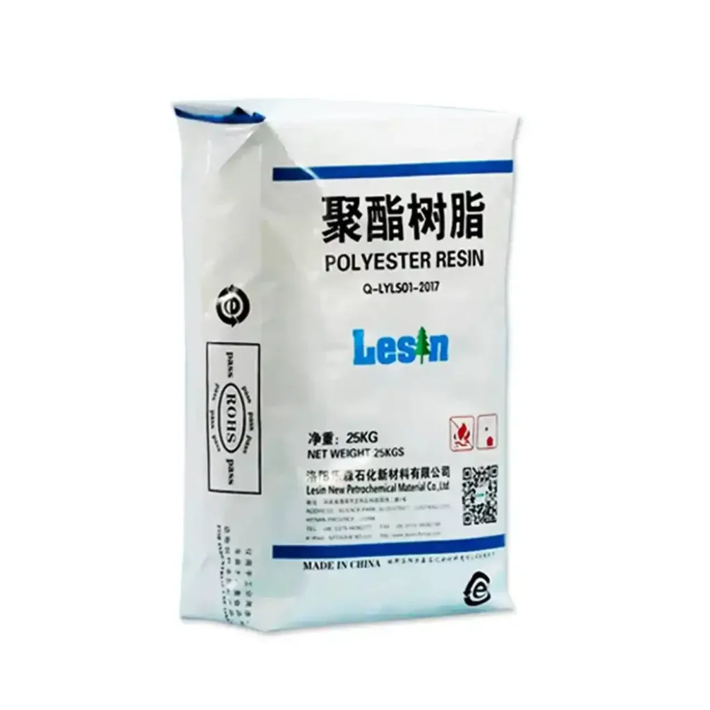
PE valve bags are heavy‑duty polyethylene sacks engineered for high‑speed, low‑dust filling on valve packers and for robust protection throughout storage and distribution. They combine a coextruded film body (typically HDPE/MDPE skins over a LLDPE or metallocene‑LLDPE core) with a self‑closing internal sleeve that is heat‑ or ultrasonically sealed after fill. This design seems simple; in practice, it re‑balances the entire packaging system. Moisture ingress slows, powder sifting recedes, pallet stability increases. When a line is constrained by humidity, hygiene, or post‑fill leakage, PE valve bags do not just contain product—they change failure probabilities.
Why does the format matter so much? Because the bag is the last barrier between a sensitive powder and a chaotic world: monsoon air, clamp trucks, tilted pallets, long haul vibration, and customers who expect zero mess. The membrane blocks vapour, the sleeve governs the leak path, and the closure removes it. Membrane, path, closure—three levers, one architecture. Some packaging answers rely on thicker paper, stickier tapes, or wishful handling; PE valve bags rely on physics you can specify, measure, and repeat.
Two practical traits set the tone: (1) low water‑vapour transmission rate (WVTR) at useful gauges (≈100–180 µm for 20–50 kg formats), and (2) weldable seals that turn a dynamic filling geometry into a dust‑tight package. Add engineered micro‑perforations for controlled de‑aeration, and the format reconciles speed with cleanliness. Is this a cure‑all? No. It is, however, a decisive lever when your powders are hygroscopic, your warehouses are humid, and your throughput targets are real.
Alternative Names and Trade Usage for PE valve bags
Markets are multilingual. Engineers say one thing, buyers another, converters a third. The following short list captures common aliases; each refers to the same core architecture:
- Polyethylene valve sacks
- Block‑bottom PE valve sacks
- PE valve‑seal bags / ultrasonic‑sealable PE valve bags
- Plastic valve bags (PE)
- Batch‑inclusion meltable PE valve bags (for additives/masterbatch)
- Heavy‑duty PE valve packaging
In sourcing conversations, you may also encounter hybrid descriptions like “WPP‑laminated valve sacks” (woven PP body, PE laminate) which are not identical to monomaterial PE valve bags but share the valve‑fill principle. When you want a quick visual catalogue to align teams, this anchor is useful: PE valve bags.
Key Characteristics of PE valve bags: Barrier, Speed, Strength, Control
What separates success from claims is not a single feature but a concert of features performing together. Below we decompose the architecture into properties you can buy, test, and tune—then recombine them into an operational strategy.
Barrier and hygiene. The coextruded film provides a continuous, low‑porosity membrane; WVTR falls well below that of porous substrates at equivalent mass, and the smooth surface reduces fibre‑shedding concerns. The valve—once sealed—eliminates the dominant leak path. Result: less caking in hygroscopic powders, fewer dusty trucks, cleaner warehouses. Is the effect visible? Yes: claims drop when the bag gives humidity fewer attack routes.
Filling dynamics. Fast lines demand de‑aeration; entrained air must escape as powders flood the bag. Because the film is tight, engineered micro‑perforations or vent channels are placed where they help during fill but do not compromise integrity later. The sleeve length and stiffness govern when the valve self‑restricts. Finally, heat or ultrasonic sealing closes the system. That sequence turns a potential contradiction—vent to fill vs seal to store—into a controlled cycle.
Mechanical survivability. Puncture, tear, and impact matter because real pallets meet real forklifts. HDPE/MDPE skins lift stiffness and abrasion; LLDPE/m‑LLDPE cores raise toughness and tear resistance. Falling‑dart impact and Elmendorf tear specifications, set at the right gauge with respectable Cpk across the web, predict how well the package endures clamp trucks, corner drops, and vibration.
Stack safety and friction. Even a heroic film will slip if the surface is too smooth. Anti‑skid emboss zones or matte skins raise slide angle and tame unit‑load shifts. In many lines this single choice—emboss or not—spells the difference between confident stacks and nervous warehouses.
Print and identity. Corona‑treated print faces enable crisp, multi‑color flexo. Product warnings remain legible after abrasion; brand color holds fast. The point is not vanity; compliance, safety, and traceability live on that surface.
End‑of‑life logic. Monomaterial bodies and valves slide naturally into PE mechanical recycling streams where collection exists. Lightweighting follows coextrusion advances, shaving grams without walking off the puncture cliff. For teams balancing EPR fees and performance, PE valve bags provide a practical path forward.
How PE valve bags Are Manufactured: From Resin Choice to Sealed Valve
PE valve bags are not born; they are engineered. Each station on the converting line sets the stage for the next. Miss one tolerance and the finale—your sealed, dust‑tight package—falls flat. Here is the choreography you can expect, rendered in plain language but anchored by real controls.
1) Resin selection and compounding. Film properties begin at the pellet. HDPE or MDPE for outer skins (stiffness, scuff), LLDPE or metallocene‑LLDPE for the core (toughness, puncture). Additives—antiblock, slip, anti‑static—are dosed tightly; excessive slip may help palletising but hurts stacking; too little and bags scuff. Incoming QC typically confirms density (ISO 1183‑1), melt flow rate (ISO 1133‑1 / ASTM D1238), and pellet moisture (ASTM D6980). Lot‑to‑lot MFR drift is the silent saboteur of film gauge and seal consistency; keep it on a leash.
2) Coextrusion and gauge control. A 3–5 layer coextrusion creates the film tube or sheet. Gauge targets for heavy‑duty sacks commonly span 100–180 µm at 20–50 kg formats. A respectable Cpk on thickness across the web makes downstream tension, valve formation, and seal energy all easier. Falling‑dart impact (ASTM D1709) and thin‑film tensile (ASTM D882) spot checks translate resin decisions into mechanical realities.
3) Printing and surface prep. Corona treatment activates the surface; dyne levels within a window secure ink anchorage. High‑contrast legibility is not cosmetic; it is regulatory—hazard statements, batch codes, recycling icons. The print station is a compliance device wearing a colorful suit.
4) Valve sleeve insertion. The internal sleeve is dimensioned to accept product quickly and then self‑restrict as head pressure collapses. Too short or too stiff and the sleeve starves the fill; too long or too soft and it flutters, inviting dust. Tolerances on sleeve width, length, and stiffness are not “tribal knowledge”; they are CTQs linked to BPM, mass variability, and leak tests.
5) Micro‑perforation and venting. Where the product and packer require de‑aeration, micro‑perfs are patterned away from high‑stress zones (corners, fold lines). Perf density might begin at 20–30 per 100 cm² and be tuned by DOE to 40–60 if the line demands more breathability. Hole diameter, distribution (staggered vs. rows), and proximity to seams are design variables, not afterthoughts.
6) Bottom formation and finishing. Block‑bottom formation gives pallets a brick‑like footprint; crease accuracy influences stack geometry. Anti‑skid emboss zones are usually applied where bags contact stretch‑hoods or neighbouring sacks.
7) Valve sealing—heat or ultrasonics. Heat bars work beautifully when pressure is uniform and dwell is controlled; ultrasonic horns deliver energy more locally, often improving channel‑leak performance on dusty lines. Peel strength (target N/25 mm) and burst at seam (kPa) are validated after conditioning and again post‑stack.
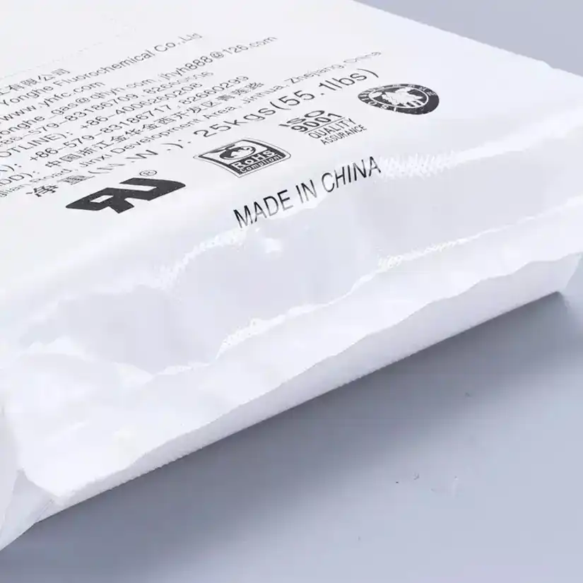
8) QA and release. A concise release suite pairs mechanical tests (tear, dart, tensile), seal tests (peel, burst, leak), and distribution simulations (drop per ISO 7965‑2 for thermoplastic sacks, compression per ISO 12048). Food‑contact runs add migration testing aligned to EU No. 10/2011 (with EN 1186 simulants) or FDA 21 CFR 177.1520, supported by supplier Declarations of Compliance. Site certification often aligns to ISO 9001 for quality management and a recognised GFSI scheme such as FSSC 22000 (Packaging Manufacturing, based on ISO 22000 + ISO/TS 22002‑4 PRPs) where food/feed use is in scope.
Where PE valve bags Win: Use Cases, Edge Conditions, and Line Realities
Applications tell the truth because they reveal trade‑offs. Below are scenarios where PE valve bags routinely out‑perform alternatives—not by fashion but by fit.
Hygroscopic powders (cement, dry‑mixes, salts). Moisture is the villain; barrier and sealed valves are the heroes. With a tight WVTR at nominal gauge and a dust‑tight valve, hydration kinetics slow and caking claims fall. Add anti‑skid emboss to calm pallets in humid warehouses.
Additives and masterbatch (including batch‑inclusion). The bag becomes a process aid. Low‑melt PE valve bags designed to disperse at ~100–110 °C remove the decant step entirely; operators no longer pour, they just toss the closed bag into the mixer. Exposure drops. Batch homogeneity rises.
Food and feed (where permitted by law and spec). When paired with compliant inks and additives, and supported by EU 10/2011 or FDA 21 CFR pathways plus FSSC 22000 site controls, PE valve bags achieve low‑dust filling and sealed edges that simplify hygiene. Migration testing and supplier DoCs are the gatekeepers here.
Fertilisers and engineered minerals. Abrasive powders punish weak films; ductile, puncture‑tolerant bodies survive clamp handling and long‑haul vibration. Valve sealing minimises sifting, and printed hazard information remains legible after abrasion.
Long supply chains, rough handling. If your route includes clamp trucks, rail, and mixed humidity, specify higher dart impact, balanced MD/TD tear, and robust valve seals. Then verify through ISO 7965‑2 drop series and ISO 12048 compression. Confidence is not a feeling; it is a pass/fail line.
Certification IDs, Third‑Party Testing, and Technical Notes for PE valve bags
Credibility comes from numbers, methods, and independent eyes. The following identifiers and practices are commonly used when qualifying PE valve bags. They anchor conversations with QA, regulators, and customers.
- Material measurements: ISO 1183‑1 (density), ISO 1133‑1 / ASTM D1238 (MFR/MVR), ISO 306 (Vicat softening), ISO 75‑1/‑2 (HDT), ISO 11357 (DSC).
- Film mechanics: ASTM D882 (thin‑film tensile), ASTM D1709 (falling‑dart impact), ISO 6383‑2 / ASTM D1922 (tear), seal peel/burst per lab SOPs.
- Distribution & unit‑load: ISO 7965‑2 (drop test for thermoplastic sacks), ISO 12048 (compression/stack), ISTA 3A/3E where retailer protocols require it.
- Food‑contact pathways: EU No. 10/2011 with migration tested via EN 1186 simulants; FDA 21 CFR 177.1520 (olefin polymers); Declaration of Compliance including simulants and time/temperature; inks/coatings compliance per supplier statements; NIAS risk screening.
- Management systems: ISO 9001 (quality), ISO 14001 (environment), ISO 45001 (OH&S). For food/feed, a GFSI scheme such as FSSC 22000 (Packaging Manufacturing—ISO 22000 + ISO/TS 22002‑4 PRPs).
- Regulatory and stewardship: REACH SVHC screening, RoHS where applicable, and country‑specific EPR declarations.
- Third‑party labs: SGS, Intertek, TÜV, and Smithers routinely run the above methods. Their reports translate internal test results into certificates customers recognise.
Do you need every badge for every SKU? No. But matching the test matrix to the actual route‑to‑market keeps you fast and honest: no under‑testing that invites risk, no over‑testing that eats time.
Specification and Parameter Summary for PE valve bags
| Parameter | Typical Window / Options | Engineering Rationale |
|---|---|---|
| Film thickness | 100–180 µm (4.0–7.0 mil) for 20–50 kg formats | Balances puncture resistance, valve formation, and material use |
| Coex structure | HDPE/MDPE skins + LLDPE or m‑LLDPE core; optional tie‑layers | Stiffness outside, toughness inside; consistent sealability |
| Valve sleeve | Internal sleeve, tuck‑in or extended; dimensional tolerance ± tight band | Controls de‑aeration during fill and seal reliability after fill |
| Valve sealing | Heat‑bar or ultrasonic; peel ≥ target N/25 mm; seam burst ≥ target kPa | Dust‑tight closure; repeatable leak performance |
| Micro‑perforation | 20–60 per 100 cm²; staggered patterns; away from stress lines | Restores airflow for high BPM without run‑propagation |
| Dart impact | Lane‑specific tiers at nominal gauge (ASTM D1709) | Predicts corner‑drop survival, clamp handling robustness |
| Tensile & elongation | Balanced MD/TD per ASTM D882 | Ensures ductile behaviour and prevents split propagation |
| Tear resistance | Elmendorf tear minima (ISO 6383‑2 / ASTM D1922) | Avoids catastrophic tears while preserving openability |
| Anti‑skid features | Emboss zones or matte skins; validated slide angle | Reduces pallet slippage under vibration/tilt |
| WVTR target | Product‑specific bands at test conditions (e.g., 38 °C/90% RH) | Directly tied to caking risk for hygroscopic powders |
| Print face | Corona‑treated; adhesion verified; high‑contrast legibility | Regulatory warnings and brand identity remain readable |
From Data to Decisions: A System for Selecting PE valve bags
How do you choose with confidence when every department wants something different? Convert preferences into measurable risks, then optimise. For each SKU, score humidity exposure, fill‑rate sensitivity, powder abrasiveness, dust classification, and route‑to‑market abuse. Run a small DOE on perf density (low/med/high), sealing method (heat/ultrasonic), and gauge (baseline/plus). Capture BPM, dust capture load, drop pass rate, sift mass loss, and leak failures after conditioning. Freeze the winner as an internal spec. This is not bureaucracy; it is how you make speed and safety shake hands.
Troubleshooting Playbook for PE valve bags
Bags sliding on pallets? Raise slide angle with embossed zones; verify stretch‑hood COF. Valve channel leaks? Dress heat bars, standardise pressure, consider ultrasonics. Split tears propagating from perf zones? Reduce hole diameter, move patterns away from corners, thicken local gauge. Dust spikes at fillers? Sleeve too stiff/short or perf density too high; adjust both. Post‑stack mass loss? Seal after settling; run go/no‑go leak tests; tighten sleeve tolerances. Each symptom maps to a small set of causes; each cause yields to a small set of countermeasures. The art is in listening to the line and reading the data.
Sustainability and Stewardship with PE valve bags
Debates about materials often turn into slogans. Reality is more nuanced. A monomaterial body and valve simplify recycling where PE streams and infrastructure exist. Lightweighting reduces grams per functional unit without surrendering drop performance. Clear on‑pack communication—material codes, disposal guidance, batch traceability—helps users do the right thing. Where regulations require recycled content or levy EPR fees, consistent specifications and supplier change control prevent unplanned property drift. Sustainability is not an afterthought; it is a design parameter that starts with the resin list and ends with a stable, recyclable bill of materials.
Why the Format Persuades: Rhetorical Yet Practical Notes on PE valve bags
Faster filling, cleaner floors, tighter pallets—three promises that sound like marketing until you put numbers beside them. Is a sealed valve really that different from a folded one? Ask the leak test. Are micro‑perfs just pinholes? Ask the BPM counter. Does embossing matter? Ask the forklift driver who catches fewer slides. Parallel claims, paired with parallel measures, produce a parallel truth: PE valve bags do not ask for faith; they ask for trials. And trials, when designed well, tend to keep their own score.
Orientation: Why PE valve bags move the needle in powder packaging
When production managers argue about moisture claims, dust alarms, and beat‑up pallets, they are really debating trade‑offs embedded in bag architecture. PE valve bags bring a distinct mix of properties—low water‑vapour transmission, weldable closures, ductile failure modes—that change how a line runs and how a product survives distribution. Are they a panacea? No. Are they a lever with outsized impact when hygroscopicity, hygiene, and post‑fill sealing are the non‑negotiables? Absolutely. This article breaks the problem into solvable parts—barrier, filling dynamics, mechanical behaviour, regulatory acceptance, sustainability, quality control—and then stitches them back together into a plant‑ready playbook. Along the way we will question assumptions, set targets, and specify tests.
PE Valve Bags 2025 Guide
Complete guide to PE valve bags, covering specifications, applications, and industry trends for industrial packaging.
Check More →PE Valve Bags Strength
Analysis on the durability and load-bearing performance of PE valve bags for bulk powder and granule packaging.
Check More →PE Valve Bags
High-quality polyethylene valve bags designed for automated filling and reliable industrial packaging solutions.
Check More →Multi-Layer Polyethylene Valve Bags
Multi-layer co-extruded PE valve bags offering enhanced barrier properties and structural integrity.
Check More →A quick signpost for readers who like to verify options: an external product family that aligns with this architecture is listed here—PE valve bags—useful for benchmarking form factors, gauges, and valve styles.
Anatomy of PE valve bags: film structure, valve geometry, and the physics they enable
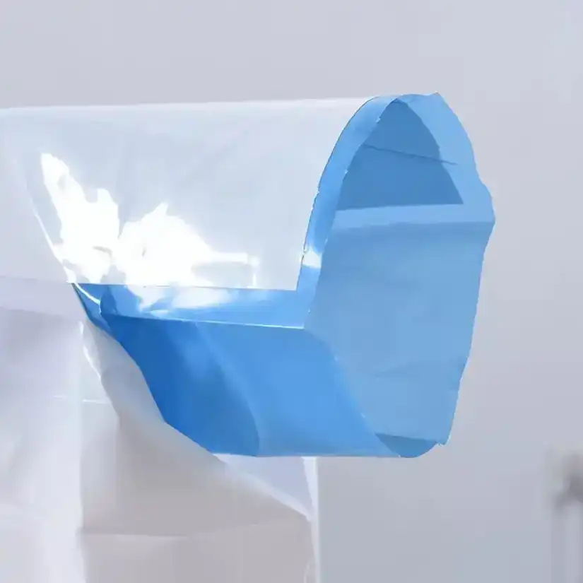
The body of PE valve bags is a coextruded film engineered for simultaneous stiffness, toughness, and sealability. Think of it as a layered argument: HDPE or MDPE outer skins for abrasion and scuff resistance; LLDPE or metallocene‑LLDPE core for toughness and puncture energy; tie‑layers (when needed) to keep it coherent; corona‑treated print face for ink anchorage. The valve sleeve—tucked, internal, or extended—is designed to admit the product, self‑restrict during settling, and then be sealed by heat or ultrasonics. That geometry seems mundane until you realise what it controls: the leak path.
Leak paths govern shelf life, dust hygiene, and after‑stack stability. The membrane (film) can be exceptionally tight; the weak link is the valve area and any venting features designed for de‑aeration. PE valve bags convert this liability into a controlled asset. They localise the venting where you intend (micro‑perforations, engineered channels) and then close it at the only place that truly matters—the valve mouth—via a heat bar or an ultrasonic horn.
The film gauges typically inhabit the 100–180 μm range for 20–50 kg formats. That is thick enough to carry puncture loads through clamp‑truck abuse, thin enough to maintain reasonable material efficiency, and still flexible for valve formation and folding. Seals are designed with an energy window generous enough to tolerate plant variability: too cold and you risk channel leaks; too hot and you embrittle the seam. Ultrasonic sealing narrows the window variation by coupling energy directly into the seal interface, a practical advantage where consistent dust‑tight closure is mandatory.
Barrier behaviour: moisture, vapour, sifting—and how PE valve bags set the odds
Consider three failure modes: moisture ingress, vapour transmission, and powder sifting. The first is catastrophic for hygroscopic products: cement softens, salts cake, functional additives clump. The second degrades performance over time, moving powders along the caking curve slowly rather than all at once. The third is a mess—dust in the truck, dust in the warehouse, dust in the customer’s feed hopper.
PE valve bags address the trio not by magic but by physics. A continuous polyolefin film exhibits low water‑vapour transmission relative to porous media. If left un‑perforated, the body contributes a strong barrier on its own. Where de‑aeration is needed, micro‑perforation creates discrete, countable apertures whose leakage can be modelled and tuned. And the valve—once sealed—removes the dominant leak pathway. The net effect is a system that can be more airtight after filling than it was during filling.
Is the improvement noticeable in the field? Ask the claims ledger. Less caking after monsoon lanes, fewer returns from damp warehouses, more predictable compressive strength in downstream materials that rely on powder quality. The correlation is practical and visible: tighter WVTR → gentler moisture sorption kinetics → fewer non‑conformances. And because the seal is weldable, repeatability increases with well‑maintained tooling rather than artisan tape jobs or prayers.
Filling dynamics on real machines: deaeration, BPM, and the paradox of venting
Filling speed feels like a simple objective—more bags per minute, fewer man‑hours per pallet. In reality it is a compromise between how fast you inject product and how fast entrained air can escape. PE valve bags are inherently tight membranes; to run fast, you introduce controlled pathways for air—micro‑perforations, valve clearances, engineered vent channels. Then you remove or close as much of that pathway as possible after the product has settled.
On impeller packers, the powder is pushed aggressively; on auger packers, it is metered more gently; on air packers, air does the heavy lifting. Each packer style interacts differently with perforation density, valve sleeve stiffness, and bag breathability. Plant trials often discover a paradox: a few more micro‑perfs restore flow and raise BPM, but beyond a threshold the extra vents lengthen settling time (and raise dust) because they become powder leakage paths rather than purely air vents. The cure is an experiment—not a guess.
The recipe is straightforward:
- Start with a conservative micro‑perf density (e.g., 20–30 per 100 cm² in a defined zone away from high‑stress corners) and map fill time, mass variability, and dust pick‑up at the reclaim filter.
- Adjust perforation size and pattern (staggered vs. rows) as variables, not afterthoughts.
- Tune valve sleeve length and stiffness; a long, soft sleeve chokes too soon, a short, stiff sleeve breathes but may not self‑seal during settling.
- Add the final act: heat‑seal or ultrasonically seal the valve and repeat mass‑leak checks after 24‑hour conditioning.
What if the target BPM refuses to budge? Then re‑shape the constraint: larger valve cross‑section, more aggressive impeller blade angle, or—if product allows—slightly coarser PSD to reduce air entrapment. PE valve bags will take the changes in stride if the body gauge and seal windows are specified with margin.
Mechanical integrity: how PE valve bags absorb abuse and keep geometry
Distribution is not a laboratory. Fork tines are not gentle; pallets do not float; clamps squeeze with enthusiasm. The mechanical survival of PE valve bags relies on a familiar trio—tensile strength, tear resistance, impact energy—and one additional, often neglected factor: friction.
The film’s MD/TD tensile profile sets how it stretches versus how it resists. A HDPE‑rich skin raises modulus and yield strength; an LLDPE‑rich core holds puncture and tear. The sticker test is the falling dart: if corner drops and random impacts do not crack the body, the product stays in the bag and the bag stays on the pallet. But even heroic film will slide if surfaces are too smooth. That is why anti‑skid emboss zones and matte skins are more than nice‑to‑haves; they are safety features for stacks exposed to vibration, tilt, and truck dynamics.
What about seal integrity? Seals fail in three ways—peel, brittle fracture, or channel leaks. Peel failure signals under‑energy or contamination. Brittle fracture points to over‑energy or incompatible film blends at the seal interface. Channel leaks betray pressure non‑uniformity. Ultrasonics largely removes the third failure by delivering energy evenly across the horn footprint, but heat bars perform just as well when pressure distribution is controlled and timing is consistent. The test regime is boring by design: peel strength at defined rates, burst at seams, and leak detection after pressure hold—then repeat after climatic conditioning.
Hygiene and contamination control: smooth surfaces, sealed edges, clean handling
There is a quiet hygiene dividend in PE valve bags. The surface does not shed fibres. The sealed valve does not weep. The edges can be welded down so that flakes and dust are not trapped in flaps. In facilities where product exposure has regulatory implications—feed, certain food ingredients, pharma intermediates—the difference shows up in environmental swabs and operator feedback. Less dust, fewer clean‑down interruptions, lower risk of cross‑contact.
A counter‑argument sometimes appears: plastic equals static, static equals dust cling. True for untreated films in dry air. The countermeasure is equally practical: additive packages that tune slip and anti‑static behaviour, and humidity‑aware handling protocols. If the bag design integrates those properties from the start, hygiene gains remain while static‑related nuisances fade.
Regulatory pathways: documentation, migration, and plant certifications
Compliance is not a sticker; it is a document set and a process. PE valve bags intended for food or feed applications travel a path that includes overall and specific migration testing under the relevant jurisdiction, supplier Declarations of Compliance that state simulants and time/temperature conditions, and plant‑level prerequisite programmes under a recognised scheme. For chemical or industrial powders, the pathway changes—fewer food‑contact tests, more emphasis on worker exposure, dust classification, and label legibility. In both worlds, change control trumps heroics; a stable formulation and a controlled converting process are worth more than exotic additives that promise the earth and deliver variability.
Sustainability and end‑of‑life: mono‑material logic, lightweighting, and practical recycling
It is tempting to frame sustainability as a paper‑versus‑plastic debate. Real life is grittier. Collection streams vary by country; EPR fees move; recycled content targets collide with mechanical performance. PE valve bags offer an honest platform for mono‑material design: a film body, a film valve, a weldable closure. That simplicity helps in two ways—first, by enabling mechanical recycling where PE streams exist; second, by allowing lightweighting without complex lamination stacks that are difficult to separate.
Can everything be recycled everywhere? Of course not. But a design that avoids mixed, inseparable layers is future‑proofed in a way multi‑material laminates are not. And because film gauges can be reduced with multi‑layer coextrusion and better resin blends, material per unit function declines while drop performance stays within spec. The carbon math improves not by rhetoric but by grams shaved and claims avoided.
Raw‑materials quality stack for PE valve bags: what to measure, how to act
Performance is won or lost at incoming inspection. The resin tells you how the film will extrude; the film tells you how the bag will absorb abuse; the valve tells you whether the bag will stay shut. A pragmatic stack looks like this:
- Resin basics: density, melt‑flow rate (MFR), pellet moisture, ash/contamination. Keep lot‑to‑lot MFR variation tight; chase moisture below process thresholds; treat ash drift as a smoke alarm.
- Film properties: thin‑film tensile in MD/TD; dart impact; tear; gauge profile across the web; gel/black‑speck counts; slip/antiblock levels. Measure, trend, and link back to drop outcomes.
- Valve and sealability: sleeve dimension tolerances, stiffness window, seal strength (peel and burst), channel‑leak tests, ultrasonic energy windows when applicable.
- Venting geometry: perforation count per area; hole diameter and shape; distance from high‑stress corner zones; correlation to fill time and dust. Control this like a critical dimension, not a tribal art.
If a batch drifts, do not guess at the line. Pull the thread back to the incoming numbers. PE valve bags are process‑sensitive, yes, but that sensitivity converts into a diagnostic advantage: when the line talks, the resin sheet music is usually attached.
Decomposition by problem type: an engineer’s way to specify PE valve bags
A large packaging programme is easier to control when every question is reframed as a small, testable question. Below is a structured map that turns generic aspirations into actionable specifications.
Moisture‑sensitive powders (salts, cement, hygroscopic additives)
Problem: Moisture ingress ruins function—caking, clumping, performance drift.
Specification moves: un‑perforated body where feasible; micro‑perf only in controlled zones; ultrasonic valve seal preferred; thicker gauge in corners or local reinforcement patches; anti‑skid bands for stack integrity under humid conditions.
Result to measure: WVTR target band at nominal gauge; sift‑loss after vibration; claim rate across humid lanes.
Fast‑fill lines starved by deaeration (fine minerals, light bulk‑density powders)
Problem: Entrained air refuses to leave; BPM stalls; dust counters spike.
Specification moves: patterned micro‑perfs with limited aperture size; valve sleeve geometry that breathes during dosing then self‑restricts as the head collapses; packer recipe tuned to the new breathability.
Result to measure: cycle time with and without perfs; dust load at reclaim; mass variability at set BPM.
Abuse‑heavy distribution (clamp trucks, long hauls, tilt in transit)
Problem: Corner punctures, seam stress, pallet slippage.
Specification moves: raise dart impact and tear targets via HDPE‑rich skins and m‑LLDPE cores; place anti‑skid emboss where unit‑load dynamics demand; widen seal‑energy window; protect perf zones from stress concentrations.
Result to measure: drop series pass rate; incident logs on clamp handling; sliding angle tests on unit loads.
Hygiene‑critical operations (feed, selected food ingredients, pharma intermediates)
Problem: Dust exposure and foreign‑matter risk.
Specification moves: smoother film skins; controlled additive package (anti‑static); full valve sealing; documented DoCs and plant PRPs under a recognised scheme.
Result to measure: environmental swab counts; valve leak tests; audit non‑conformance frequency.
Product parameter table for PE valve bags (typical engineering windows)
| Parameter | Typical Window / Practice | Why it matters |
|---|---|---|
| Film thickness | 100–180 μm for 20–50 kg formats | Balances puncture resistance and material use; supports valve forming |
| Coex structure | HDPE/MDPE skins + LLDPE/m‑LLDPE core | Stiffness outside, toughness inside; sealability retained |
| Dart impact (free‑falling) | Set by lane; example tiers at nominal gauge (e.g., Method A ≥ defined g) | Predicts survival in corner drops and random impacts |
| MD/TD tensile & elongation | Balanced profile per ASTM thin‑film methods | Ensures ductile behaviour, avoids split‑propagation |
| Tear resistance (Elmendorf) | Minimums tuned to avoid run‑propagation while allowing openability | Prevents catastrophic tears in transit |
| Valve sleeve | Dimensional tolerance ± tight band; stiffness window defined | Governs deaeration during fill and seal reliability after fill |
| Valve sealing | Heat bar or ultrasonic; peel ≥ target N/25 mm; burst ≥ target kPa | Determines dust‑tight closure and shelf‑life |
| Micro‑perforation density | 20–60 per 100 cm² in zoned patterns (where used) | Restores airflow for deaeration without uncontrolled leaks |
| Anti‑skid features | Emboss bands or matte skin; target slide angle defined | Keeps pallets stable under vibration and tilt |
| WVTR at nominal gauge | Target band set per product (e.g., sub‑1 g/m²·day at 38 °C/90% RH when un‑perforated) | Links directly to caking risk in humid lanes |
| Print face | Corona‑treated side; adhesion verified | Branding legibility and ink durability |
Numbers are set during plant DOEs; the table lists starting windows that practitioners tighten with data.
Case‑pattern analysis: repeating problems, repeatable cures with PE valve bags
Hygroscopic cement in tropical lanes
The complaint trail reads like a detective story: pallets arrive caked, compressive strength depressed, sack corners bruised. What changed? Ambient moisture and time. The cure with PE valve bags is systematic: limit perf count, push ultrasonic sealing on the valve, thicken corners in the die‑cut, and validate with drop series at elevated humidity. The cost? A few grams of film and a sealing station; the payoff is a near‑vanishing claim rate and pallets that stack like bricks instead of sponges.
Fine mineral fillers on an impeller packer
Throughput is king until dust becomes queen. Operators observe a paradox: adding more micro‑perfs enables faster fill yet raises dust. The resolution is tighter aperture control and repositioning the perf zone away from the stress lines that open under dynamic load. PE valve bags cooperate because the film’s ductility allows re‑patterning without catastrophic tear propagation; the valve seal eliminates sifting once the material settles.
Carbon‑black masterbatch and batch inclusion
Here the win is ergonomic and environmental. Empty‑bag handling used to coat operators and floors in soot. Batch‑inclusion PE valve bags—engineered to melt and disperse in the mixer—remove the decant step entirely. No open pouring; no empty sacks to manage; fewer airborne particles. The polymer must soften at processing temperature yet survive distribution—an apparent contradiction resolved by thoughtful resin choices and tuned bag gauges.
From numbers to knobs: driving OEE with PE valve bags
Overall Equipment Effectiveness rises when variability falls. PE valve bags reduce three forms of noise: moisture‑driven variability in product properties, dust‑driven trips on sensors and housekeeping delays, and leak‑driven mass variability after stacking. The control levers are in your hands: gauge Cpk, perf geometry, seal energy. Audit fills by cycle time components—dosing, deaeration, settling, sealing—and attack the longest segment first. Retune in small increments, observe, and lock the gains with SOPs. What cannot be measured cannot be controlled; what cannot be controlled will eventually be blamed on the bag.
Troubleshooting atlas for PE valve bags: symptom → cause → countermeasure
- Symptom: Bags slide during transport.
Likely cause: Smooth skins, low slide angle, excessive stretch‑hood lubrication.
Countermeasure: Add anti‑skid emboss in contact zones; switch to matte exterior; raise hood film COF. - Symptom: Channel leaks at the valve.
Likely cause: Uneven heat‑bar pressure or contaminated sleeve.
Countermeasure: Dress the bar, standardise pressure profile, clean sleeve feed path; consider ultrasonic sealing. - Symptom: Split tears propagating from perf area.
Likely cause: Perf pattern intersecting high‑stress lines; oversized apertures.
Countermeasure: Re‑pattern perfs away from corner stress fields; reduce hole diameter; thicken local gauge. - Symptom: Dust spikes at filler.
Likely cause: Perf density too high; sleeve too stiff or too short.
Countermeasure: Reduce perf count; change sleeve stiffness; lengthen sleeve to self‑restrict later in the fill. - Symptom: Post‑stack mass loss.
Likely cause: Valve not fully sealed; channel leak after settling.
Countermeasure: Validate seal timing after settling; move to ultrasonic; add go/no‑go leak test at end‑of‑line.
Plant validation protocol: designing experiments for PE valve bags
A credible validation is short, sharp, and statistically honest. Design two to three factors at two to three levels: perf density (low/medium/high), valve sealing method (heat/ultrasonic), and film gauge (baseline/plus). Measure line BPM, dust capture load, bag mass variability, drop‑test pass rate, and sift loss after vibration. Analyse interactions—does higher perf density only work at the thicker gauge? Does ultrasonic sealing erase post‑stack sifting even when perf density rises? Close the loop with a risk review and a locked specification.
Why the emphasis on interaction effects? Because packaging is a system. You do not run film, valve, and packer in isolation; you run all three at once, under a calendar, with operators who deserve tools that forgive small human deviations. PE valve bags behave generously when specified generously.
Procurement and supplier governance for PE valve bags: practical checkpoints
- Supplier quality system maturity and change‑control discipline.
- Resin family stability (documented windows for MFR, density, additive packages).
- Coex capability and thickness control Cpk across the web.
- Perforation methods and measurement capability (hole count, diameter, pattern repeatability).
- Valve sleeve manufacturing tolerances and seal‑energy calibration.
- Traceability from resin lot to finished bag lot with retained samples.
Buying bags by the kilo invites surprises; buying by a locked functional specification turns a bag into an engineered component that can be sourced from multiple qualified vendors without re‑learning expensive lessons.
Cross‑industry comparisons: what PE valve bags inherit and what they improve
From flexible film packaging they inherit weldability and barrier. From rigid packaging they borrow the idea of dimensional stability through engineered stiffness. From paper sacks they learn about deaeration as a first‑class requirement. PE valve bags synthesise these: they add barrier where paper is porous, they add weldability where paper relies on adhesives, they add ductile failure where rigid formats shatter. The result is not a victory of one material over another but a portfolio that allows engineers to choose with intent. For moisture‑sensitive, hygiene‑critical, abuse‑exposed lanes, the intent often points to PE valve bags.
Implementation checklist for operations teams using PE valve bags
- Lock incoming QC windows for resin and film; trend MFR, gauge, dart, tensile.
- Fix a baseline perf geometry; run DOE around it; freeze the winning pattern.
- Validate valve sealing at worst‑case dust loads; pick heat or ultrasonic on evidence, not on habit.
- Add anti‑skid where unit‑load dynamics demand; verify slide angle on real pallets.
- Audit distribution with drop series and climatic conditioning that reflect reality, not wishful thinking.
- Train operators on SOPs tied to the chosen parameters; enforce change control.
Each check is simple. Together they turn PE valve bags from commodity film sacks into tuned, repeatable packaging machinery—machinery made of polymer and process rather than gears and belts.
Framing the Problem Space Around PE valve bags
Packaging for powders and granular materials is a multi‑constraint engineering problem: moisture control, clean filling, mechanical survival, regulatory acceptance, and cost all interact. PE valve bags enter this landscape as a system component rather than a generic container. They reduce water‑vapour ingress through a continuous polyethylene film, allow high‑speed charging via a self‑closing valve, and finish with a weldable seal that transforms an open path into a controlled barrier. The central question is not whether PE valve bags work, but under what conditions they outperform alternatives and what specifications make the difference between marginal and outstanding performance.
Method: A Problem‑Driven, Closed‑Loop Approach for PE valve bags
We use an “introduction → methods → results → discussion” pattern to avoid hand‑waving and keep the argument falsifiable.
Introduction: Stakeholders define competing outcomes—operations want throughput, quality wants fewer claims, EHS wants lower dust exposures, marketing wants printable real estate, procurement wants predictable cost. PE valve bags must reconcile these without creating new failure modes.
Methods: Decompose requirements into measurable sub‑problems: (1) barrier (WVTR, leak path at valve), (2) filling dynamics (deaeration, settling time, mass repeatability), (3) mechanical survival (dart impact, tear, seal strength), (4) hygiene (dust retention, fibre shedding), (5) compliance (migration, DoC, site PRPs), (6) end‑of‑life (mono‑material recyclability). For each, set a testable hypothesis and a dial we can turn—gauge, coex structure, perforation density, sleeve geometry, seal energy.
Results: When tuned deliberately, PE valve bags cut moisture‑related claims, push bags‑per‑minute upwards without runaway dust, and keep unit loads stable. They also create a more deterministic sealing step compared with purely adhesive closures.
Discussion: The architecture is not a universal solvent—fine powders may still prefer higher venting windows; paper’s native porosity can be faster in some fillings. Yet with micro‑perforation geometry, a balanced coex, and ultrasonic or precise heat sealing, the gap narrows while barrier advantages remain. The logic loop closes when the same measures that diagnose problems (WVTR, drop pass rate, dust capture load) also verify improvements.
System Boundaries: Where PE valve bags Touch the Value Chain
Horizontally across functions, PE valve bags connect resin suppliers, film lines, converters, filling equipment, logistics, and end users. Vertically within the product, they unify polymer chemistry, film mechanics, valve geometry, and seal physics. The boundary selection matters: ignore resin MFR stability and you chase gauge variation downstream; neglect clamp‑truck dynamics and you under‑spec dart impact; omit valve sealing from validation and you inherit channel leaks in the field. A system view ensures PE valve bags are specified as engineered components with traceable cause‑and‑effect, not as commodities.
Physical Principles That Give PE valve bags Their Edge
Barrier: Continuous polyolefin films possess low water‑vapour transmission compared with porous substrates at similar mass. That is not marketing; it is diffusion physics. Add a sealed valve and the quickest moisture path is removed.
Ductility: Polyethylene blends (HDPE skins, LLDPE/m‑LLDPE cores) absorb energy without brittle fracture, protecting contents from corner drops and clamp pressure.
Weldability: Heat and ultrasonic sealing convert an open geometry into a repeatable closure. Because the seal energy window is controllable, process capability can be measured and maintained.
Friction: Smooth films can slip; emboss or matte zones raise slide angle. Stability is a surface phenomenon as much as a structural one.
Translating Requirements Into Parameters for PE valve bags
Barrier targets become WVTR bands and seal‑leak thresholds. Filling targets become perf density and sleeve stiffness windows. Mechanical targets become dart impact levels and MD/TD tear balance. The conversion from desire to number is where projects succeed. For PE valve bags, the high‑leverage parameters are:
• Film gauge (typically 100–180 μm for 20–50 kg): too thin and puncture risk rises; too thick and sealing window narrows and cost climbs.
• Coex recipe: HDPE/MDPE outside for stiffness and scuff; LLDPE/m‑LLDPE inside for toughness and tear; tie layers only when necessary.
• Micro‑perforation density and pattern: start conservative (20–30/100 cm²), then DOE toward 40–60/100 cm² if fill is starved; keep holes away from stress lines and corners.
• Valve sleeve geometry: length, width, and stiffness determine when the valve breathes and when it self‑restricts; tolerance is a CTQ.
• Valve sealing method: heat bars need uniform pressure; ultrasonics deliver energy precisely and often improve channel‑leak results.
• Anti‑skid features: emboss placement where bags meet neighbour bags or stretch hoods; validate slide angle empirically.
Horizontal Thinking: Comparing Adjacent Solutions Without Losing Focus
While the goal is not to catalogue other materials, thinking horizontally clarifies trade‑offs. PE valve bags outperform porous papers on moisture barrier but need engineered venting to match very high filling speeds. Woven PP laminates can be extremely tough but add interfaces that complicate recycling and sealing repeatability. Rigid containers beat every sack on crush resistance but lose in cube utilisation and cost per fill. This cross‑domain comparison prevents over‑engineering in one dimension while under‑serving another.
Vertical Thinking: From Pellet to Pallet With PE valve bags
Pellet: Density (ISO 1183‑1) and MFR (ISO 1133‑1/ASTM D1238) windows constrain processability; moisture (ASTM D6980) ensures stable extrusion.
Film: Thin‑film tensile (ASTM D882), dart impact (ASTM D1709), and tear (ISO 6383‑2/ASTM D1922) link recipe to abuse resistance.
Conversion: Sleeve tolerances, perf geometry, and bottom formation accuracy forecast filling speed and stack geometry.
Sealing: Peel strength (N/25 mm) and seam burst (kPa) after conditioning reflect closure reliability; ultrasonic energy settings or heat‑bar dwell provide the control knobs.
Distribution: Drop (ISO 7965‑2 for thermoplastic sacks) and compression (ISO 12048) validate survival; vibration and sift mass‑loss tests expose fines leakage.
Stakeholder Stories That Anchor PE valve bags in Reality
Operations: “We need BPM without dust alarms.” Translation: deaeration geometry and sleeve stiffness must be tuned, then sealed to eliminate sifting afterward.
Quality: “Stop moisture claims.” Translation: WVTR and valve‑leak thresholds must be set and verified; corner gauge and seal windows must reflect hot/humid lanes.
EHS: “Lower exposure.” Translation: micro‑perfs that vent air but not fines; sealed edges; anti‑static additives where justified.
Procurement: “Predictable cost.” Translation: locked specs across multiple qualified suppliers; Cpk on gauge and perf counts; change‑control discipline.
The Filling Paradox and How PE valve bags Resolve It
Fast filling needs air to escape, but long shelf life needs the system sealed. The paradox dissolves when venting is treated as a controllable, temporary property: perforations and valve clearance during dosing; closure by heat or ultrasonics after settling. Designers decide where, how many, and how large the vents are—and then remove their effect. The payoff is BPM with hygiene, not BPM or hygiene.
Optimization Patterns for PE valve bags on Real Packers
Impeller packers reward small, frequent micro‑perfs away from high‑stress lines; auger packers are sensitive to sleeve restriction timing; air packers may need larger valve cross‑sections but benefit greatly from ultrasonic sealing after a brief dwell. In each case, you tune three variables—perf geometry, sleeve stiffness/length, and sealing method—while monitoring four metrics: cycle time, dust capture load, mass variability, and leak failures after conditioning. A limited DOE uncovers interactions (e.g., a thicker film tolerates more perfs without split propagation).
Mechanical Survival: Why PE valve bags Resist Real‑World Abuse
Fork tines impact corners; clamps squeeze; pallets shift under vibration. PE valve bags survive because ductile films distribute stress, balanced MD/TD tear resists run propagation, and anti‑skid surfaces turn kinetic energy into frictional stability. The tests are familiar but essential—ASTM D1709 for impact, D882 for tensile, D1922/ISO 6383‑2 for tear, ISO 7965‑2 for drop—and the acceptance bands are set by the worst lanes, not the easiest ones.
Hygiene and Cleanlines: The Quiet Advantages of PE valve bags
Smooth films do not shed fibres, sealed valves prevent weeping, and welded flaps reduce crevices. Add controlled anti‑static behaviour and housekeeping improves. Environmental swabs drop not because of slogans but because pathways for dust and foreign matter have been removed.
Regulatory Logic: Documentation, Migration, and Plant Readiness for PE valve bags
Where food/feed contact is in scope, plastics must meet EU No. 10/2011 (with EN 1186 migration testing) or FDA 21 CFR 177.1520 for olefin polymers. Declarations of Compliance reference simulants and time/temperature regimes. Sites typically operate under ISO 9001 for quality and a GFSI scheme like FSSC 22000 (Packaging Manufacturing; ISO/TS 22002‑4 PRPs) to systematize sanitation and traceability. For industrial chemicals, the emphasis shifts to label legibility, dust hazard classification, and worker exposure—but the sealing and barrier advantages remain.
Sustainability and Stewardship: The End‑of‑Life of PE valve bags
Mono‑material bodies and valves simplify mechanical recycling where PE streams exist. Lightweighting follows advances in coextrusion and metallocene catalysts, shaving grams while holding dart impact. EPR fees respond to mass and recyclability; PE valve bags can be engineered to minimise both without sacrificing performance. Clear on‑pack identification closes the loop for users.
Use‑Case Map: Where PE valve bags Shine
Hygroscopic powders (cement, salts, dry‑mixes): low WVTR film + sealed valve = slower caking kinetics.
Additives/masterbatch (batch inclusion): low‑melt films that disperse at ~100–110 °C eliminate decant and reduce exposure.
Fertilisers and engineered minerals: abrasion‑resistant skins and robust tear balance handle clamp trucks; sealed valves reduce sifting.
Food/feed (where permitted): compliant inks/additives + site PRPs enable low‑dust filling and hygienic closure.
Long, rough routes: higher dart tiers, anti‑skid emboss, and ultrasonic sealing stabilise unit loads.
Troubleshooting Atlas for PE valve bags
Bags sliding on pallets → Emboss or matte skin; verify slide angle with stretch‑hood film.
Channel leaks at valve → Uniform bar pressure or ultrasonic horn; clean sleeve path; validate peel/burst after conditioning.
Split tears from perf area → Reduce hole diameter; move pattern; increase local gauge or change pattern to staggered.
Dust spikes at filler → Sleeve too stiff/short or perf density too high; adjust both; retune packer.
Post‑stack mass loss → Seal after sufficient settling; tighten sleeve tolerances; add leak go/no‑go at end‑of‑line.
Data‑Backed Parameter Summary for PE valve bags
| Parameter | Typical Window / Practice | Why it matters |
|---|---|---|
| Film thickness | 100–180 μm (4.0–7.0 mil) for 20–50 kg formats | Balances puncture resistance and material use; supports valve forming |
| Coex structure | HDPE/MDPE skins + LLDPE/m‑LLDPE core | Stiffness outside, toughness inside; sealability retained |
| Dart impact (ASTM D1709) | Lane‑specific tiers at nominal gauge | Predicts survival in impacts and clamp handling |
| Thin‑film tensile (ASTM D882) | Balanced MD/TD yield/break/elongation | Ensures ductile behaviour, avoids split propagation |
| Tear (ISO 6383‑2 / ASTM D1922) | Minima tuned to prevent run tears | Prevents catastrophic damage while preserving openability |
| Micro‑perfs | 20–60 per 100 cm², staggered, away from corners | Restores airflow for deaeration without uncontrolled leaks |
| Valve sleeve | Tight dimensional tolerance; stiffness window defined | Governs deaeration timing and seal reliability |
| Valve sealing | Heat or ultrasonic; peel ≥ target N/25 mm; seam burst ≥ target kPa | Delivers dust‑tight closure and shelf life |
| Anti‑skid features | Emboss/matte zones; validated slide angle | Keeps pallets stable under vibration/tilt |
| WVTR target | Product‑specific bands at 38 °C/90% RH | Directly tied to caking risk for hygroscopic powders |
| Print face | Corona‑treated; adhesion verified | Branding and safety information stay legible |
Integrating the Pieces: A Practical Selection Flow for PE valve bags
- Classify SKU risk: humidity exposure, dust exposure class, abrasiveness, food/feed contact, route severity.
- Shortlist design moves: thicker gauge for abuse lanes; perf geometry for fill‑rate constraints; ultrasonic sealing where dust‑tight closures are mandatory; anti‑skid for unstable pallets.
- Run a minimal DOE: perf density (low/med/high) × seal method (heat/ultrasonic) × gauge (baseline/plus). Measure BPM, dust capture load, drop pass rate, sift mass loss, leak failures after conditioning.
- Freeze specifications: lock resin windows (MFR, density), perf geometry, sleeve tolerances, seal energy windows, acceptance bands for dart/tensile/tear.
- Govern suppliers: ISO 9001 required; for food/feed, FSSC 22000 Packaging Manufacturing recommended; change‑control SLAs; retained samples and traceability from resin lot to finished lot.
- Monitor and learn: SPC on gauge and seal; quarterly migration checks where relevant; annual re‑qualification of critical CTQs.
Cross‑Functional Communication Using PE valve bags as a Common Denominator
Operations speak in BPM and changeover minutes; quality speaks in AQLs and Cpk; procurement in lead time and ladder pricing; sales in claims and customer delight. PE valve bags unify the dialogue because they convert high‑level asks into measurable dials. A shared SPEC, a shared test plan, and a shared set of CTQs turn debates into experiments and experiments into decisions.
Strategic Positioning and Internal Link for PE valve bags
For alignment across teams and vendors, it helps to point to a concrete representation of the architecture. See: PE valve bags for a visual benchmark of heavy‑duty, form‑fill‑seal tubular roll polyethylene bags used in valve applications. This anchor is not an endorsement; it is a convenient common picture for specification workshops.
Discussion: What Changes When You Commit to PE valve bags
The operations calendar changes—less time firefighting dust and leaks, more time optimising cycle segments. The QA dashboard changes—fewer moisture complaints and cleaner trend lines on drop tests after conditioning. The sustainability ledger changes—mono‑material logic at end‑of‑life, grams shaved through coex optimisation. Most importantly, the culture changes—from reactive fixes to proactive specification. PE valve bags are not just packaging; they are a method for turning variability into parameters and parameters into performance.
References (non‑CNC sources)
• ISO 1183‑1: Plastics — Methods for determining the density of non‑cellular plastics.
• ISO 1133‑1 / ASTM D1238: Plastics — MFR/MVR determination.
• ASTM D882: Standard Test Method for Tensile Properties of Thin Plastic Sheeting.
• ASTM D1709: Standard Test Method for Impact Resistance of Plastic Film by the Free‑Falling Dart Method.
• ISO 6383‑2 / ASTM D1922: Tear properties of plastic film.
• ISO 7965‑2: Sacks — Drop test of filled sacks — Part 2: Sacks made from thermoplastic flexible film.
• ISO 12048: Packaging — Complete, filled transport packages — Compression and stacking tests.
• EU No. 10/2011: Plastics materials and articles intended to come into contact with food; EN 1186 migration testing series.
• FDA 21 CFR 177.1520: Olefin polymers — conditions for safe use in contact with food.
• FSSC 22000 (Packaging Manufacturing): Scheme requirements (ISO 22000 + ISO/TS 22002‑4 PRPs).
• TAPPI T460 / ISO 5636‑5: Air permeance (Gurley method) — reference for deaeration context in paper alternatives.
• SGS / Intertek / TÜV: Typical third‑party laboratories providing film mechanicals, migration testing, and packaging validation services.
• Industry converters’ public technical pages on PE valve sacks and micro‑perforation practices (e.g., ultrasonic‑sealable valves, anti‑skid emboss, block‑bottom formation) for parameter benchmarking.