
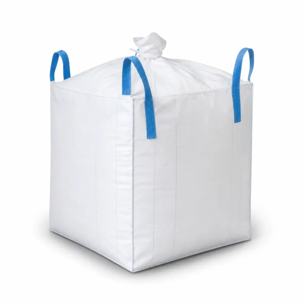
Jumbo Bag Product Analysis: From Filling Interface to Polypropylene Tape Strength
A jumbo bag looks simple only when it is empty. Once it is filled, lifted, moved, stacked, stored, and discharged, every design choice begins to speak: the top controls filling, the bottom controls release, the body controls shape, the loops control handling, and the polypropylene tape controls the strength behind all four. From VIDEPAK’s market perspective, the right product is therefore not “a standard bag with a few options.” It is a working system built around the customer’s powder, granule, equipment, route, risk level, and cost target.
Core product principle: specify the bag from the process outward, not from the catalog inward. A reliable Jumbo bags manufacturer first asks what must happen during filling, lifting, storage, and emptying; only then should fabric weight, denier, seams, liners, and accessories be fixed.
Product Positioning and Design Logic
VIDEPAK positions FIBC jumbo bags as ton-grade woven polypropylene containers for dry bulk transport, with customizable tops, bottom, constructions, lifting systems, liners, and electrostatic types. Its public product range identifies top choices including Open Top, duffle Top, flap top, and filling spout; bottom choices including Flat Bottom, Duffle Bottom, and Discharge spout; body choices including U-panel, circular, four-panel, and baffle; and handling choices including four loop and tunnel lift systems. VIDEPAK also presents load capacities from about 500 kg to 2,000 kg for project-specific designs.
The market value of this modular approach is clear. One customer may need fast loader-bucket filling and one-time bottom cutting. Another may need a dust-controlled filling station and measured discharge into a mixer. A third may care most about cubic shape because freight is paid by container space. The bag may carry the same nominal weight in all three cases, yet the best specification will be different. Good packaging begins with comparison; great packaging ends with fit.
The Commercial Question Behind Every Technical Choice
Fill faster
Choose an opening that matches the filler, lets air escape correctly, and reduces manual tying or repositioning.
Lift safer
Match loop geometry to forklift tines, cranes, available headroom, and the operator’s normal approach angle.
Store tighter
Use body architecture and baffles to control bulge, pallet fit, wall contact, and container utilization.
Empty cleaner
Select the outlet for the required balance of speed, metering, residue control, worker access, and dust.
This systems view also matches the current ISO framework. ISO 21898:2024 covers material, construction, design, type testing, marking, selection, and safe use for FIBCs carrying non-dangerous solids and lifted from above. Safe Working Load is not a marketing phrase: it is the rated load the bag is designed to carry, while the safety factor expresses the relationship between that rated load and required test performance. FIBCA terminology commonly presents 5:1 or 6:1 safety-factor ratios, with the final class and use conditions stated on the approved label and specification.
Interface Options from Filling to Emptying
Top Options: Four Ways to Control Entry
Open Top
An Open Top bag leaves the full upper cross-section accessible. It is the most direct answer for loader buckets, chutes with variable position, large irregular pieces, construction materials, landscaping products, and operations where filling speed matters more than enclosure. The wide opening makes visual inspection easy and reduces the need to align a narrow inlet. It also gives the operator room to level material. The trade-off is equally direct: the contents are less protected from rain, dust escape, foreign matter, and product loss unless a separate cover, liner closure, or wrapping step is added. Choose Open Top when the material is robust, the environment is controlled, and the filling method is broad or imprecise. Do not choose it simply because it is the cheapest top; choose it because openness is useful.
duffle Top
A duffle Top adds a light fabric skirt around the full bag opening. During filling, the skirt can remain wide and flexible; after filling, it can be gathered and tied. This design sits between a fully open bag and a fixed filling spout. It accepts wider variation in chute position and diameter than a narrow spout, while offering better post-fill coverage than an Open Top. It is useful for flakes, granules, agricultural goods, recycled material, and medium-dust applications where complete sealed transfer is not required. The key specification points are skirt height, coating, tie style, seam reinforcement, and whether the skirt must fit around the outside of a filling head. A taller duffle Top offers more gathering room, but unnecessary fabric adds cost and can interfere with loops or automated handling.
Flap Top
A flap top uses an attached fabric panel to cover the upper opening after filling. It can be made as a simple protective flap, a full-width lid, or a closure designed to be tied, sewn, or secured with fasteners. Compared with a duffle Top, it avoids a gathered neck and can create a flatter finished profile. Compared with an Open Top, it gives better protection against dirt and light weather exposure. The flap is not automatically dust-tight or moisture-tight; those results depend on overlap, coating, seam layout, liner use, and closure method. It suits customers who need broad filling access but want a defined cover that is quick to close and easy to reopen for inspection.
Filling Spout
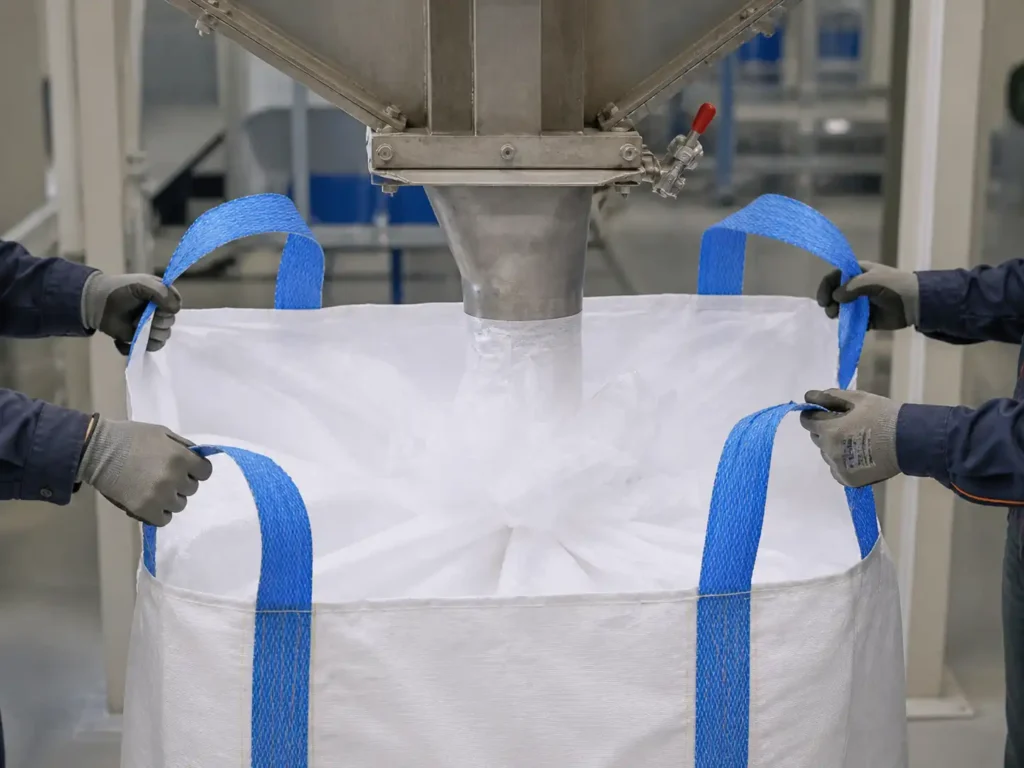
A filling spout creates a controlled cylindrical inlet that can be tied, clamped, or connected to a filling head. It is the preferred interface when the customer wants cleaner transfer, better dust capture, more repeatable automation, and stronger protection after closure. The spout diameter should match the equipment outlet and the product’s required feed rate; its length should provide enough material for clamping and tying without folding into the product stream. Fine powders may also require coated fabric, sift-resistant seams, a liner, or a separate venting path because a tight spout can trap air during fast filling. In other words, the filling spout controls entry, but airflow controls performance. VIDEPAK’s product architecture treats filling spouts and duffle openings as configurable interfaces rather than fixed catalog parts.
Bottom Options: Three Different Discharge Strategies
Flat Bottom
A Flat Bottom is a closed base with no built-in outlet. It gives a simple, strong platform and removes the seam complexity of a discharge neck. It is suitable when the bag will be cut open, tilted, vacuum-emptied, or treated as a one-way package. It is also common when discharge control happens through external equipment rather than through the bag. The strength is simplicity; the weakness is limited reuse and reduced control once the base is cut.
Duffle Bottom
A Duffle Bottom opens a large part, or nearly all, of the base. It is designed for very fast and near-complete release of products that do not need precise metering. The broad opening can reduce residue and help with bulky or poorly flowing contents, but it creates a large flow event, so the receiving hopper, support frame, and closure system must be planned together. Speed is the benefit. Control is the trade-off.
Discharge spout
A Discharge spout provides a defined outlet for controlled emptying. Diameter, length, tie method, safety flap, and outlet reinforcement are adjusted to the product’s flow and the receiving equipment. Free-flowing pellets can use a standard cylindrical neck; fine powder may need sift-resistant sewing and a liner outlet; cohesive material may require a larger or conical transition. The outlet should be accessible without forcing an operator beneath an unsupported load.
Bottom-selection flow
The bottom must be evaluated as part of the emptying station, not in isolation. VIDEPAK’s engineering guidance links flat bases to cut-and-tilt unloading, standard outlets to controlled flow, and full-opening bottoms to rapid total discharge. FIBCA also defines remote-opening outlets as systems that allow release without the operator reaching under the bag, an important direction whenever the site’s risk assessment calls for better separation between worker and suspended load.
Structural Choices for Shape and Handling
Constructions: U-Panel, Circular, Four-Panel, and Baffle
Construction decides how forces travel through the body and how the bag changes shape under load. U-panel, circular, and four-panel describe the main body pattern. A baffle is different: it is an internal shape-control feature that can be added to a suitable base construction. VIDEPAK lists all four as core product choices and describes internal baffles as a way to lock a filled bag closer to a cubic form.
U-Panel Construction
One continuous fabric piece forms two opposite side walls and the bottom, while two separate panels close the remaining sides. This creates a strong load path through the base and offers a practical balance of cost, durability, printable area, and customization. U-panel bags work with most top and bottom styles, liners, coatings, and conventional corner-seam loops. They generally retain a more square profile than a plain circular body, though they can still bulge when filled with dense or highly flowable material. For a broad industrial program, U-panel is often the balanced answer: not the fewest seams, not the highest shape control, but strong, adaptable, and familiar.
Circular Construction
A circular, or tubular, body is woven as a continuous tube, so the main side walls do not need vertical panel seams. Fewer body seams can reduce potential sift paths and simplify conversion. The term “circular” describes how the fabric is made, not a requirement that the filled package be round. Even so, without internal baffles the walls tend to bow outward more than a well-built U-panel or four-panel design. Circular construction pairs naturally with cross-corner loops and is attractive for high-volume applications where efficient production, reduced side-seam count, and good general performance matter more than perfect cube shape.
Four-Panel Construction
Four individual side panels are sewn together and joined to a separate bottom. This geometry creates clear vertical corners and broad, flat faces, supporting good shape retention, detailed printing, and controlled dimensioning. The price of that control is more sewing: more seams require disciplined seam allowance, thread tension, stitch density, and inspection. Four-panel construction is a strong choice when presentation, pallet alignment, label visibility, and a defined rectangular footprint are important. It is especially useful for customers who want the bag to behave more like a flexible box without giving up the low tare weight and foldability of woven polypropylene.
Baffle Construction
Baffles are internal fabric panels sewn near the corners, with openings that allow product to move through the bag while restricting outward wall expansion. The result is a more cubic filled profile, better footprint discipline, and often better use of pallet, rack, truck, and container space. Baffles do not replace the structural body; they manage its shape. They must be designed around product flow, filling speed, cleanability, and liner geometry. Very large or poorly placed openings weaken shape control; very small openings can slow filling or trap material. Baffles cost more, but when freight cube, stack alignment, or automated warehousing is the main cost driver, the return can exceed the added bag price.
Lifting Loops: The Connection Between Bag and Machine
Loops are not handles added at the end. They are structural load paths. Webbing strength, loop free height, stitching length, reinforcement zones, panel orientation, and forklift geometry must be designed together. FIBCA defines reinforced sections as areas where extra warp yarns support loop attachment, and it notes that SWL results from the combined design of fabric, sewing, and construction.
Four Loops
The standard four-point system gives one lifting point at each upper corner. It distributes the load around the bag and works with common forklifts, cranes with spreaders, and many filling frames. All four loops must be engaged as intended. It is flexible and widely understood, but handling speed depends on whether the loops stand open and how easily the tines enter.
Tunnel Lifting
Tunnel or sleeve loops create broad channels for forklift tines. The operator inserts the forks through the sleeves rather than picking up four separate loops. This can improve speed, alignment, and handling in repeatable warehouse routes. It requires a close match to tine width, thickness, spacing, and entry direction; it is less flexible when different lifting equipment is used.
Cross Corner Loop
Cross-corner loops are commonly integrated with circular bodies and arch over each corner. Their geometry tends to hold the loop more upright, making tine entry faster and reducing manual loop positioning. They suit high-throughput forklift handling, provided the fork spacing and loop dimensions are correct. Their benefit is access; their engineering task is even force transfer into the tubular body.
Corner Loop
Corner, side-seam, or loop-over-loop designs are sewn into the vertical seams of U-panel or four-panel bodies. They create a direct connection between webbing and reinforced seam zones and can provide excellent strength. The loops may lie flatter than cross-corner designs, so pickup can require more operator care or loop supports on the filling frame. Their benefit is robust integration with sewn-panel bodies.
Handling rule: never choose loops from a photograph alone. Provide tine dimensions, spacing, entry direction, lifting height, crane or forklift type, headroom, desired pickup speed, and whether all four points can remain vertical during the lift. The approved SWL and handling instructions must govern actual use. FIBCA’s safe-handling guidance advises users to follow the supplier’s application-specific instructions rather than treating general guidance as a substitute for the bag specification.
Material Engineering, Selection Matrix, and Future Direction
Polypropylene, Tape Denier, and the Real Meaning of Strength
The structural shell is normally made from woven polypropylene tapes. Resin is melted into film, slit into narrow tapes, drawn so the polymer chains become more oriented, stabilized, and then woven into fabric. The finished body may be uncoated for airflow, extrusion-coated for improved sift and moisture control, or combined with a polyethylene liner for stronger containment or hygiene. VIDEPAK describes the process as a controlled chain from tape-grade resin testing through extrusion, orientation, weaving, conversion, and lot traceability.
Denier is a measure of linear mass: one denier equals one gram per 9,000 metres of tape or yarn. In practical buying language, a higher denier usually means more mass per unit length and often a thicker or heavier tape. It does not, by itself, guarantee a stronger bag. Tape width, draw ratio, molecular orientation, resin quality, filler content, weave density, fabric GSM, coating, seam construction, loop reinforcement, bag dimensions, and test results all influence final performance. Denier is one voice in the choir; it is not the whole song. ISO 1144 sets the textile linear-density system and conversion principles, while ASTM D1907/D1907M covers practical determination of yarn linear density.
Why denier matters: it changes the amount of polymer carried by each tape, the tape’s cross-section, the way load spreads through the weave, the fabric’s puncture and tear behavior, and the amount of material available around a stitch hole. Yet higher denier can also reduce flexibility, change weave balance, and add unnecessary resin when the structure is not optimized.
For heavy-duty FIBC projects, VIDEPAK’s technical pages present indicative working windows around 160–240 g/m² for many single-trip builds and roughly 1,000–1,500 denier for the woven tapes, while other VIDEPAK guidance shows broader one-ton fabric ranges around 140–300+ g/m² and about 700–1,200 denier depending on load, abrasion, bag size, and construction. These are engineering starting points, not universal purchase specifications. A compact 1,000 kg bag carrying smooth pellets may need a different fabric from a tall 1,000 kg bag carrying sharp mineral pieces, even though the label weight is identical.
The weakest point may not be the fabric. It may be the loop-to-body joint, the seam around a Discharge spout, a cut edge, a poorly supported liner, or a sharp forklift tine. This is why a professional Jumbo bags manufacturer should report the complete specification: resin basis, tape denier, tape width, warp and weft count, uncoated GSM, coating weight, tensile and elongation data, seam type, thread, loop webbing, SWL, safety factor, dimensions, tolerance, UV requirement, and validation standard. ISO 21898:2024 places materials, construction, design, type tests, and marking in one framework because safe performance belongs to the whole package, not to one attractive number.
VIDEPAK specification workflow
Material choice also includes electrostatic behavior. A basic polypropylene shell does not automatically provide protection in an explosive atmosphere. IEC 61340-4-4:2018 covers classification, labeling, inner liners, test methods, design requirements, performance, and safe use for FIBCs in hazardous explosive environments. Therefore, Type A, B, C, or D selection must follow the product, dust or gas zone, minimum ignition risk, liner, grounding method, and operating procedure; it must never be reduced to color or a generic “anti-static” claim.
The same discipline applies to sustainability. Lower fabric weight is useful only when the bag still passes the required tests and protects the product. A baffle may add material but reduce transport cube. A liner may complicate recycling but prevent moisture damage. A stronger loop patch may add grams but prevent a lost load. The best environmental choice is often the design that avoids failure, product waste, rework, and extra transport. Reduce where evidence allows; reinforce where risk demands. This reflects VIDEPAK’s broader design position that preventing product loss can outweigh simple material-minimization claims.
Final product view
VIDEPAK’s competitive product story is not a single fabric or a single bag style. It is the ability to combine Open Top, duffle Top, flap top, or filling spout with Flat Bottom, Duffle Bottom, or Discharge spout; then match that interface set to U-panel, circular, four-panel, or baffle construction and to four-loop, tunnel, Cross Corner Loop, or Corner Loop handling. Underneath every combination sits the same engineering duty: turn polypropylene tape, seams, webbing, and test evidence into predictable field performance.
That is what buyers should expect from a serious Jumbo bags manufacturer: not more options for the sake of options, but clearer choices, verified strength, easier operations, and a bag that fits the process from first fill to final discharge.
- Jumbo Bag Product Analysis: From Filling Interface to Polypropylene Tape Strength
- Product Positioning and Design Logic
- Interface Options from Filling to Emptying
- Structural Choices for Shape and Handling
- Material Engineering, Selection Matrix, and Future Direction
- Polypropylene, Tape Denier, and the Real Meaning of Strength
- 1. Technological Innovations in Jumbo Bag Manufacturing
- 2. Material Science: Balancing Strength and Sustainability
- 3. Customization: Tailoring Bags to Industry Needs
- 4. Future Trends: Smart and Sustainable Packaging
- 5. VidePak’s Manufacturing Excellence
- 6. FAQs: Addressing Critical Concerns
“How can jumbo bags evolve to meet the demands of modern industries while balancing sustainability and customization?”
This question drives innovation in bulk packaging. Jumbo bags, or Flexible Intermediate Bulk Containers (FIBCs), now integrate advanced materials like high-density polypropylene (PP), precision printing technologies, and modular designs to deliver unmatched durability, branding versatility, and eco-efficiency. At VidePak, our 30+ years of expertise and cutting-edge manufacturing infrastructure position us at the forefront of this transformation. Let’s explore how technological breakthroughs and material science are redefining jumbo bag performance.
1. Technological Innovations in Jumbo Bag Manufacturing
Modern jumbo bags are engineered to withstand extreme loads (up to 2,000 kg) while ensuring safety and compliance. VidePak’s Austrian Starlinger machinery enables high-speed production of PP woven fabric with tensile strengths exceeding 1,500 N/5 cm, critical for industries like construction and agriculture.
Type A B C D FIBC Jumbo Bags
Complete classification of jumbo bags with advanced material technologies and safety standards for industrial use.
Check More →Anti-Static FIBC Bags in Food Industry
Innovative anti-static technology for jumbo bags, ensuring safe and compliant bulk packaging applications.
Check More →Anti-Bulge FIBC Jumbo Bags
Advanced structural technology for jumbo bags, improving weight capacity and sustainable packaging performance.
Check More →FIBC Jumbo Bags Solutions
Customized jumbo bag solutions with cutting-edge materials, technology, and future-oriented industrial design.
Check More →Key Technological Advancements:
- Automated Weaving: 100+ circular looms produce fabric with 14×14 weave density/cm², reducing material waste by 12% compared to traditional methods.
- Lamination Techniques: 30+ lamination machines apply BOPP or PE coatings (20–40 μm) to enhance moisture resistance by 95%, ideal for fertilizers and chemicals.
- Seam Reinforcement: Ultrasonic sealing and 3-stitch lock patterns prevent seam failure, as demonstrated in a 2024 trial where VidePak’s bags maintained integrity under 1.8x rated load.
2. Material Science: Balancing Strength and Sustainability
2.1 Polypropylene (PP) Innovations
VidePak uses virgin PP resin to comply with FDA and EU food-contact standards, avoiding contaminants common in recycled materials. Additives like UV stabilizers extend outdoor lifespan by 30%, critical for agricultural storage.
Case Study: A Brazilian soybean exporter reduced spoilage by 22% using VidePak’s UV-treated PP bags with 120 gsm fabric, which blocked 99% of UV radiation during 6-month outdoor storage.
2.2 Eco-Friendly Alternatives
VidePak’s 30% recycled PP blends reduce carbon footprint by 18%, aligning with the Ellen MacArthur Foundation’s circular economy goals. Trials with bio-based PE coatings (derived from corn starch) aim for 50% fossil-fuel polymer replacement by 2027.
3. Customization: Tailoring Bags to Industry Needs
3.1 Dimensional Flexibility
Jumbo bags are customizable in size, with standard dimensions optimized for logistics:
| Capacity | Dimensions (L x W x T) | Industry Use Case |
|---|---|---|
| 500 kg | 90x90x120 cm | Construction aggregates |
| 1,000 kg | 110x110x150 cm | Bulk chemicals |
| 1,500 kg | 130x130x180 cm | Mining ores |
Data sourced from VidePak’s 2024 client portfolio.
3.2 Precision Printing Solutions
VidePak’s 30+ high-definition printing machines support CMYK, Pantone, and RAL color systems, enabling full-surface branding with 0.1 mm registration accuracy. A German fertilizer brand reported a 15% sales increase after adopting 360° UV-resistant prints showcasing nutrient diagrams.
Printing Parameters:
- Ink Adhesion: Water-based inks achieve 4/5 ASTM D3359 cross-hatch scores, ensuring longevity in humid environments.
- Color Fastness: Prints retain 95% vibrancy after 12 months of UV exposure, per ISO 105-B02 testing.
4. Future Trends: Smart and Sustainable Packaging
4.1 Smart Liners
Embedded QR codes and RFID tags enable real-time tracking, reducing supply chain losses by 25%. VidePak’s pilot with a Dutch logistics firm cut inventory discrepancies by 18% using NFC-enabled liners.
4.2 Biodegradable Materials
Research into PLA-PP hybrids aims to achieve 80% compostability by 2030, addressing landfill concerns. Early trials show 6-month degradation in industrial composting facilities.
4.3 Anti-Static and Fire-Resistant Designs
VidePak’s carbon-coated PP fabrics dissipate static charges (surface resistivity <10^9 Ω/sq), critical for flammable powder storage.
5. VidePak’s Manufacturing Excellence
Founded in 2008, VidePak combines 30+ years of industry expertise with scalable production:
- Global Reach: $80M annual revenue, serving 45+ countries including key markets in Europe and Southeast Asia.
- Capacity: 8 million bags/month via 100+ circular looms and 16 extrusion lines.
- Certifications: ISO 9001, BRCGS, and FSSC 22000 for food-grade packaging.
6. FAQs: Addressing Critical Concerns
Q1: How do I select the right liner thickness for corrosive chemicals?
A: For acids like HNO₃, opt for 80 μm PE liners with anti-static additives. VidePak provides SGS-tested compatibility reports.
Q2: Can jumbo bags withstand -30°C temperatures?
A: Yes. Our LLDPE-lined bags retain flexibility at -30°C, validated in Arctic oilfield trials.
Q3: Are customized sizes cost-effective for small orders?
A: VidePak’s modular designs allow cost-efficient runs of 500+ units, with 10-day lead times.
References
- Global Agricultural Packaging Report, 2024.
- VidePak Case Study: UV-Resistant Bags in Brazilian Agriculture.
- ASTM D3359 Standard Test for Ink Adhesion.
- Circular Economy in Packaging, Ellen MacArthur Foundation.
- ISO 105-B02 Color Fastness Testing Protocols.
External Links
- Explore advanced manufacturing processes for jumbo bags.
- Discover customizable polypropylene solutions.
Authored by VidePak’s Marketing Team | March 6, 2025